DA50S/DA55S/DA70S/DA75S AddressRight™ Printers Service Manual
5-7
Removal & Replacement • 5
DA50S/DA55S (WS51/WS56) Parts Removal
1. Remove operator and non-operator side covers (see section 5.2).
2. Remove main processor board/grounding sheet assembly (see section
5.4).
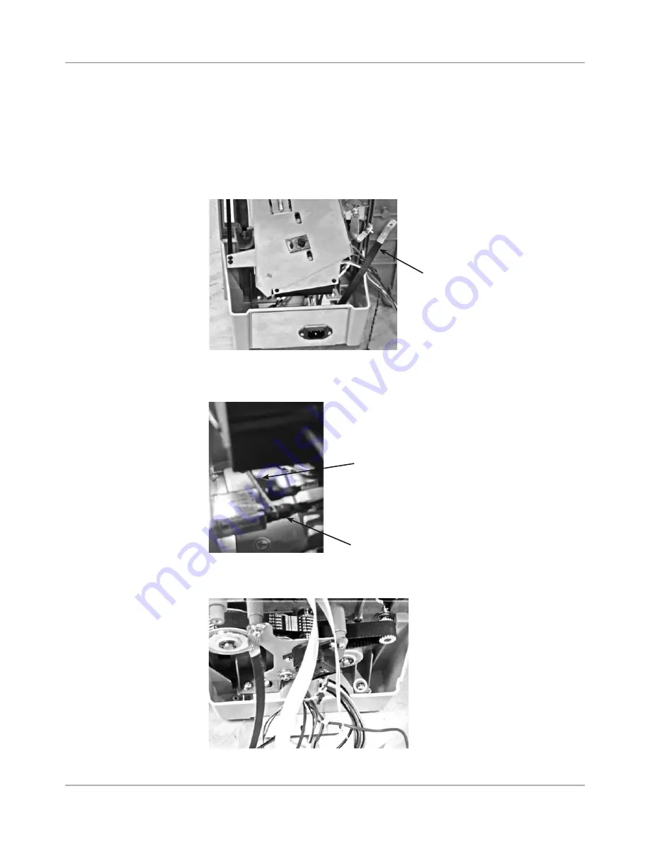
3. On non-operator side, remove P18, P5, and P6 junction connectors.
4. Remove ground strap (furthest on the right with black sleeve), see photo.
5.7 Paper
Transport
Motor/Belt
5. Remove three main power cables to AC inlet. Use screwdriver or needle
nose pliers to pry off from each spade lug (see photo below).
6. Remove two phillips screws holding blue side chassis to bottom gray tray
(see photo below). Do for both sides of machine (four screws total).
Ground
Strap
Using Screwdriver
to Pry Cables from
Spade Lugs (3)
Side Chassis Attachment
to Gray Tray (screw loca-
tions in circles)
Spade Lug
Содержание AddressRight DA50S
Страница 6: ...Table of Contents vi SV61831 Rev A DA50S DA55S DA70S DA75S AddressRight Printers Service Manual ...
Страница 20: ...2 10 SV61831 Rev A DA50S DA55S DA70S DA75S AddressRight Printers Service Manual 2 Specifications ...
Страница 42: ...4 16 SV61831 Rev A DA50S DA55S DA70S DA75S AddressRight Printers Service Manual 4 Troubleshooting Diagnostics ...


