CDJ-800MK2
102
1
2
3
4
1
2
3
4
C
D
F
A
B
E
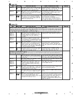
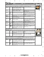
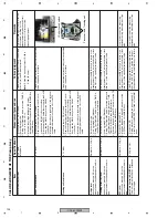
Error codes (1/2)
Sites
Waveforms
Points to be checked
Causes & Measures to be taken
Remarks
E-6002
DSP PROGRAM DOWNLOAD ERROR
At the time of initialization, the program was not downloaded (written) to the EEPROM on the AUDIO DSP. There may be a factor
that hampers normal initialization of the EEPROM on the AUDIO DSP at the time of power on. The possible cause is defective state
of 3-wire serial lines that are commonly used by the MPU and the FPGA, AUDIO DSP, and DACs.
The data on this symptom are not stored in the internal memory.
MAIN Assy
MAIN Assy
, ,
Check the waveforms of the 3-wire serial lines
(CLK, DATA, DSPDREQ) to confirm that the
configuration procedures are properly performed.
Chip fracture or soldered portion of IC lead lifted
off the board on the line where the waveform
does not change is most likely the cause. In the
former case, replace the chip. In the latter case,
soldering touchup is needed.
E-7201
TOC READ ERROR
Table of Contents (TOC) data cannot be read.
This symptom is associated with the reading accuracy of the servo motor of the CD player.
Player
Measure the error rate in Player Operation mode
of Service mode. To which the cause is
attributed, disc or player, must be judged first.
For measuring, play back the lead-in point
indicated in the error code by listening the sound.
Follow the procedures described in "The error
rate measured in Test Operation mode of
Service mode is high."
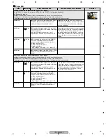
E-8301
PLAYER ERROR (Startup error)
• E830112: The desired address could not be searched for.
• E830115: The address could not be read.
• E830122: The focus servo could not be closed.
• E830191: The pickup did not return toward the inner tracks.
If the above-mentioned error codes are indicated before the loaded disc is recognized as a CD, the disc will be automatically
ejected. This symptom is associated with the reading accuracy of the servo motor of the CD player.
Player
z
Measure the error rate in Player Operation
mode of Service mode. For the error codes other
than E830191, proceed to Step
c
.
MAIN Assy
MAIN Assy
x
Check the waveform at the INSIDE Test Land
near CN102, by changing the positions of the
Inside switch. Does the signal change between
low and high according to the switch settings?
If the signal does not change, a defective Inside
switch, solder fracture, soldered portion lifted off
of the surface mount on the line, and loose
connection of the FFC cables are likely causes.
Player
c
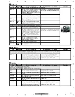
Visually check if the joint spring on the TM
Assy is deformed. Also check for the sliding
smoothness of the slider.
If the joint spring is deformed or displaced or if
the slider moves abnormally smoothly, replace
the pickup.
Player
v
Measure the error rate in Player Operation
mode of Service mode. To which the cause is
attributed, disc or player, must be judged first.
For measuring, play back the lead-in point
indicated in the error code by listening the sound.
Follow the procedures described in "The error
rate measured in Test Operation mode of
Service mode is high."
E-8302
PLAYER ERROR (Abnormality in playback)
• E-830212: The desired address could not be searched for.
• E-830215: The address could not be read.
• E-830222: The focus servo could not be closed.
This symptom is associated with the reading accuracy of the servo motor of the CD player.
Player
Measure the error rate in Player Operation mode
of Service mode. To which the cause is
attributed, disc or player, must be judged first.
For measuring, play back the lead-in point
indicated in the error code by listening the sound.
Follow the procedures described in "The error
rate measured in Test Operation mode of
Service mode is high."
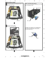
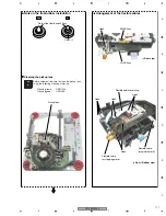
Slider
Joint spring
26
10
32 34
Содержание CDJ-800MK2
Страница 27: ...CDJ 800MK2 27 5 6 7 8 5 6 7 8 C D F A B E MODE MODE 3 3 A 27 24 26 19 36 ...
Страница 29: ...CDJ 800MK2 29 5 6 7 8 5 6 7 8 C D F A B E Data PANEL DATA Digital A 2 3 3 3 A 3 3 A 23 ...
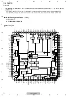
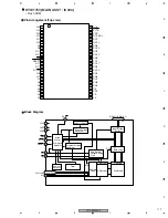
Страница 119: ...CDJ 800MK2 119 5 6 7 8 5 6 7 8 C D F A B E SCF5249LAG140 MAIN ASSY IC301 32 bit RISC MPU Block Diagram ...
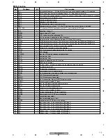
Страница 130: ...CDJ 800MK2 130 1 2 3 4 1 2 3 4 C D F A B E Pin Function ...
Страница 135: ...CDJ 800MK2 135 5 6 7 8 5 6 7 8 C D F A B E Pin Function ...
Страница 138: ...CDJ 800MK2 138 1 2 3 4 1 2 3 4 C D F A B E PE8001A MAIN ASSY IC702 DAC IC Pin Arrangement Top view Block Diagram ...
Страница 139: ...CDJ 800MK2 139 5 6 7 8 5 6 7 8 C D F A B E Pin Function ...
Страница 143: ...CDJ 800MK2 143 5 6 7 8 5 6 7 8 C D F A B E ...
Страница 153: ...CDJ 800 7 5 6 7 8 5 6 7 8 C D F A B E ...
Страница 174: ...CDJ 800 28 1 2 3 4 1 2 3 4 C D F A B E 3 7 JFLB SLDB and JOGB ASSYS I JFLB ASSY DWG1565 I CN500 F ...
Страница 180: ...CDJ 800 34 1 2 3 4 1 2 3 4 C D F A B E ...
Страница 200: ...CDJ 800 54 1 2 3 4 1 2 3 4 C D F A B E 6 ADJUSTMENT There is no information to be shown in this chapter ...

