CDJ-800MK2
86
1
2
3
4
1
2
3
4
C
D
F
A
B
E
7. GENERAL INFORMATION
7.1 DIAGNOSIS
7.1.1 SERVICE MODE
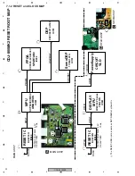
1.The outline in service mode
This machine is controlled by two microcomputers, a display microcomputer and a player microcomputer, and test mode is prepared for
each. A display microcomputer performs processing to a button input, display of FL, and lighting of LED. A player microcomputer drives
a player.
[1] Check mode of a button and a display function of a display microcomputer.
It is the mode which checks a button input and a display function.
[2] Check mode of the load of JOG dial
It is the mode which measures the load when rotating JOG dial.
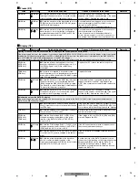
[3] Check mode of operation of a player microcomputer
It is the mode which performs the check of the mechanism and serbo of a player microcomputer of operation.
This mode consists of "player operation mode" and "test operation mode."
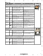
[4] Version check mode
It is the mode which can check the version of the software of each microcomputer.
[5] Error display list / Error display mode
The history of the contents of an error can be checked to 16 pieces.
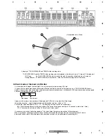
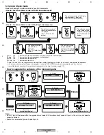
2.Check mode of a button and a display function of a display microcomputer.
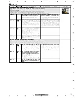
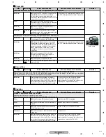
In this mode, it can check whether a display microcomputer can be made to turn on partially as follows, the input of each button and
volume is normal, and a display is normal. In addition, a display is turned on only while pushing the button.
If a TOUCH/RELEASE knob is made into states other than the maximum (right-hand side), it will become the check mode of button and
display function, and if each button is pushed, FL display and LED which correspond light up.
Moreover, if a knob is made into the maximum (right-hand side) and arbitrary buttons are pushed once, it will become JOG load check
mode and top speed and time will be displayed on a FL dot-matrix part. (After-mentioned)
PLAY/PAUSE
CUE
IN/REALTIME CUE
OUT/OUT ADJAST
RELOOP/EXIT
FOLDER <-
FOLDER ->
TRACK (|<<)
TRACK (>>|)
REV (<<)
FWD (>>)
BEAT LOOP 1
BEAT LOOP 2
BEAT LOOP 4
BEAT LOOP 8
JOG MODE
TEMPO
MASTER TEMPO
QUICK RETURN
TIME MODE/AUTO CUE
TEXT MODE
DELETE
MEMORY
EJECT
CUE/LOOP CALL <
CUE/LOOP CALL >
REVERSE
TOUCH SENSOR
JOG rotating to FWD
JOG rotating to REV
PLAY
CUE
IN
OUT
RELOOP
FOLDER <-
FOLDER ->
TRACK |<<
TRACK >>|
REV <<
FWD >>
BEAT 1
BEAT 2
BEAT 4
BEAT 8
JOG MODE
TEMPO
MASTER TE
QUICK RET
TIME/ACUE
TEXT MODE
All FL lights up
MEMORY
EJECT
CALL <
CALL >
REVERSE
TOUCH SW
JOG >
< JOG
1G lights up
(1)
(2)
(3)
(5)
All FL lights up
(4)
PLAY/PAUSE
CUE
IN/REALTIME CUE
OUT/OUT ADJAST
RELOOP
BEAT LOOP 1
BEAT LOOP 2
BEAT LOOP 4
BEAT LOOP 8
VINYL
TEMPO 10%/WIDE
MASTER TEMPO
QUICK RETURN
All LED lights up
REV
Button, Switch
FL Dot-matrix display
FL Other display
Light up LED
FL Display
E
S R V I C E
TEMPO
MEMORY
POWER ON
Содержание CDJ-800MK2
Страница 27: ...CDJ 800MK2 27 5 6 7 8 5 6 7 8 C D F A B E MODE MODE 3 3 A 27 24 26 19 36 ...
Страница 29: ...CDJ 800MK2 29 5 6 7 8 5 6 7 8 C D F A B E Data PANEL DATA Digital A 2 3 3 3 A 3 3 A 23 ...
Страница 119: ...CDJ 800MK2 119 5 6 7 8 5 6 7 8 C D F A B E SCF5249LAG140 MAIN ASSY IC301 32 bit RISC MPU Block Diagram ...
Страница 130: ...CDJ 800MK2 130 1 2 3 4 1 2 3 4 C D F A B E Pin Function ...
Страница 135: ...CDJ 800MK2 135 5 6 7 8 5 6 7 8 C D F A B E Pin Function ...
Страница 138: ...CDJ 800MK2 138 1 2 3 4 1 2 3 4 C D F A B E PE8001A MAIN ASSY IC702 DAC IC Pin Arrangement Top view Block Diagram ...
Страница 139: ...CDJ 800MK2 139 5 6 7 8 5 6 7 8 C D F A B E Pin Function ...
Страница 143: ...CDJ 800MK2 143 5 6 7 8 5 6 7 8 C D F A B E ...
Страница 153: ...CDJ 800 7 5 6 7 8 5 6 7 8 C D F A B E ...
Страница 174: ...CDJ 800 28 1 2 3 4 1 2 3 4 C D F A B E 3 7 JFLB SLDB and JOGB ASSYS I JFLB ASSY DWG1565 I CN500 F ...
Страница 180: ...CDJ 800 34 1 2 3 4 1 2 3 4 C D F A B E ...
Страница 200: ...CDJ 800 54 1 2 3 4 1 2 3 4 C D F A B E 6 ADJUSTMENT There is no information to be shown in this chapter ...

