CDJ-800MK2
104
1
2
3
4
1
2
3
4
C
D
F
A
B
E
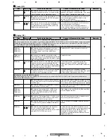
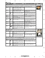
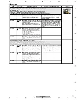
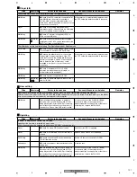
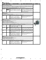
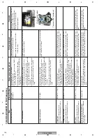
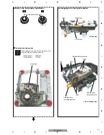
FAILURE JUDGMENT OF THE Pickup Assy
LD short-circuit switch
Focus coil and Tracking coil
Item
Specifications
Measurement procedures
Failure judgment
Remarks
Laser Diode (LD) current
Typ 70 mA
Max 80 mA
1
Make sure that no CD is loaded.
2
Enter Service mode.
3
During Test Operation mode, press the TEMPO
button to turn the LD on.
4
Measure the voltage difference (DC value)
between the Test Lands LD3S and LDCHECK on
the MAIN Assy.
If the measurement result of the LD current is 80
mA or more, the LD is deteriorated.
Note:
Check the mounting status of R101 to
R104 (22 ohms).
To prevent damage to the LD, after the
LD is turned on (Step 3 of the
measurement procedures and after),
never connect or disconnect the
measuring equipment.
Focus coil resistance
3.4
±
0.5
Ω
1
Make sure that no CD is loaded.
2
Remove the bottom plate and set the LD short-
circuit switch (S1101) to Short-circuiting.
3
Disconnect the FFC cable that connects the RLYB
Assy and the MAIN Assy from the CN101
connector.
4
Measure the conductor resistance of the terminal
assembly between Pins 13 and 14 of the FFC
cable.
If the measurement result is beyond the specified
value, the pickup is in failure.
Tracking coil resistance
4.1
±
0.6
Ω
1
Make sure that no CD is loaded.
2
Remove the bottom plate and set the LD short-
circuit switch (S1101) to Short-circuiting.
3
Disconnect the FFC cable that connects the RLYB
Assy and the MAIN Assy from the CN101
connector.
4
Measure the conductor resistance of the terminal
assembly between Pins 15 and 16 of the FFC
cable.
If the measurement result is beyond the specified
value, the pickup is in failure.
S-curve level
Usually use a pressed CD, as the
measurement result depends on the disc
type.
Reference: 1.5 Vp-p
1
Enter Service mode.
2
Load a pressed CD. (Standby)
3
During Test Operation mode, press the TIME, A,
then CUE buttons to send a command.
The pickup or the MAIN Assy is in failure if the
measurement result is more than double or less
than 50% of the specified (reference) value.
Tracking Error (TE) level
Usually use a pressed CD, as the
measurement result depends on the disc
type.
Reference: 1.1 Vp-p
1
Enter Service mode.
2
Load a pressed CD. (Standby)
3
During Test Operation mode, press the buttons in
the following order to send a command: TIME,
TEMPO, RELOOP, then LOOPIN twice.
4
Measure the peak-to-peak TE waveform at the TE
Test Land on the MAIN Assy.
The pickup or the MAIN Assy is in failure if the
measurement result is more than double or less
than 50% of the specified (reference) value.
RFO level
Usually use a pressed CD, as the
measurement result depends on the disc
type.
Reference: 1.2 Vp-p
1
Play back a pressed CD.
2
Measure the peak-to-peak RF waveform at the
RFO Test Land on the MAIN Assy.
The pickup or the MAIN Assy is in failure if the
measurement result is more than double or less
than 50% of the specified (reference) value.
You may disconnect the measuring
equipment during measurement, if you
wish.
Auto Gain Control (AGC) RF level
The measurement result does not depend
on the disc type.
1.2 Vp-p
±
10 %
1
Play back a CD.
2
During playback, measure the peak-to-peak RF
waveform at the AGCRF Test Land on the MAIN
Assy.
If the RFO level is within the specified values,
and if the AGC RF level is outside the range of
the specified values, the MAIN Assy is in failure.
You may disconnect the measuring
equipment during measurement, if you
wish.
Содержание CDJ-800MK2
Страница 27: ...CDJ 800MK2 27 5 6 7 8 5 6 7 8 C D F A B E MODE MODE 3 3 A 27 24 26 19 36 ...
Страница 29: ...CDJ 800MK2 29 5 6 7 8 5 6 7 8 C D F A B E Data PANEL DATA Digital A 2 3 3 3 A 3 3 A 23 ...
Страница 119: ...CDJ 800MK2 119 5 6 7 8 5 6 7 8 C D F A B E SCF5249LAG140 MAIN ASSY IC301 32 bit RISC MPU Block Diagram ...
Страница 130: ...CDJ 800MK2 130 1 2 3 4 1 2 3 4 C D F A B E Pin Function ...
Страница 135: ...CDJ 800MK2 135 5 6 7 8 5 6 7 8 C D F A B E Pin Function ...
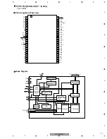
Страница 138: ...CDJ 800MK2 138 1 2 3 4 1 2 3 4 C D F A B E PE8001A MAIN ASSY IC702 DAC IC Pin Arrangement Top view Block Diagram ...
Страница 139: ...CDJ 800MK2 139 5 6 7 8 5 6 7 8 C D F A B E Pin Function ...
Страница 143: ...CDJ 800MK2 143 5 6 7 8 5 6 7 8 C D F A B E ...
Страница 153: ...CDJ 800 7 5 6 7 8 5 6 7 8 C D F A B E ...
Страница 174: ...CDJ 800 28 1 2 3 4 1 2 3 4 C D F A B E 3 7 JFLB SLDB and JOGB ASSYS I JFLB ASSY DWG1565 I CN500 F ...
Страница 180: ...CDJ 800 34 1 2 3 4 1 2 3 4 C D F A B E ...
Страница 200: ...CDJ 800 54 1 2 3 4 1 2 3 4 C D F A B E 6 ADJUSTMENT There is no information to be shown in this chapter ...

