23 On-the-fly marking
9.
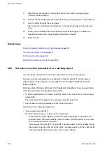
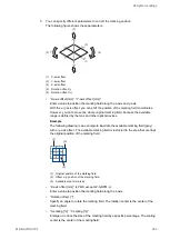
Measure the distance between the center of the marking field and the trigger
detecting position. Enter the measured value in the “Trigger detecting position [mm]”
text box.
(1)
(3)
(4)
(5)
(6)
(2)
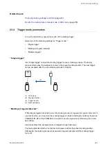
(1) Marking field center
(2) “Trigger detecting position [mm]”: Distance between the center of the marking field and the
trigger detecting position
(3) Moving direction
(4) Trigger sensor
(5) Workpiece
(6) Trigger detecting position
10.
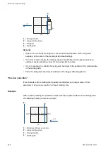
Measure the distance (d) between the trigger detecting position and the marking start
position on the workpiece.
Make sure that the distance between the workpiece reference boundary and the
marking data in the marking field corresponds with the measured distance (d). If
required, adjust the position of the workpiece reference boundary or the marking data.
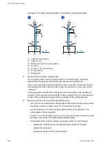
Example 1: The trigger detecting position is in front of the marking start position.
ME-NAVIS2-OP-1
251


