24 System settings
“X-scaling [%]”/“Y-scaling [%]”: 100
• Select “Apply to laser marking system” in the ribbon to save the settings.
After finishing the calibration, enter the system offset parameters used before.
6.
For “Head direction to axis”, set the head direction to “No. 1”.
7.
Select “Marking field calibration” in the ribbon.
8.
In the dialog, select “Test marking/guide laser”.
9.
Select the “Test marking” tab.
The values for laser power, scan speed, pulse cycle and pulse duration (LP-RV), set
in the selected marking file, are displayed. If you want to perform the test marking with
other laser settings, change them in the “Marking settings” screen.
10.
Select the “Guide laser” tab. For “Guide laser display”, set “Marking image” and select
“Guide laser ON”.
Check the marking position and place the marking target at a work distance of
190mm.
11.
Select “Start marking” to trigger the laser radiation.
A confirmation dialog appears. Select “Yes” to start laser radiation.
When the test marking ends, leave the marking target at the same position.
12.
In the “Guide laser” tab, set “Marking field” for “Guide laser display”. Select “Guide
laser ON”.
13.
Compare the marking field position indicated by the guide laser with the actual
marked position of the marking field. If they do not overlap, enter correction values in
the “Marking field calibration” dialog to adjust the position of the marking laser.
Specify any of the following parameters:
• “X-offset [mm]”, “Y-offset [mm]”: Enter a value to move the center position of the
marking field.
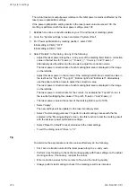
• “Distortion correction”: For each distortion correction shape, you can specify X and
Y values to change the marking field.
• Select “Apply”.
The new settings will be updated in the laser marking system.
• To reset all values to the initial settings, select “Reset to default”.
14.
Repeat steps 10 to 13 until the marking field position indicated by the guide laser is
aligned with the actual marked position of the marking field.
Related topics
Adjust the marking field position
Details of distortion correction settings
278
ME-NAVIS2-OP-1

