2
Connecting Cameras
32
4.
Confirm the camera image (see page 38)
5.
Place the BB-HGW700A and the cameras (see page 41)
2.3.2
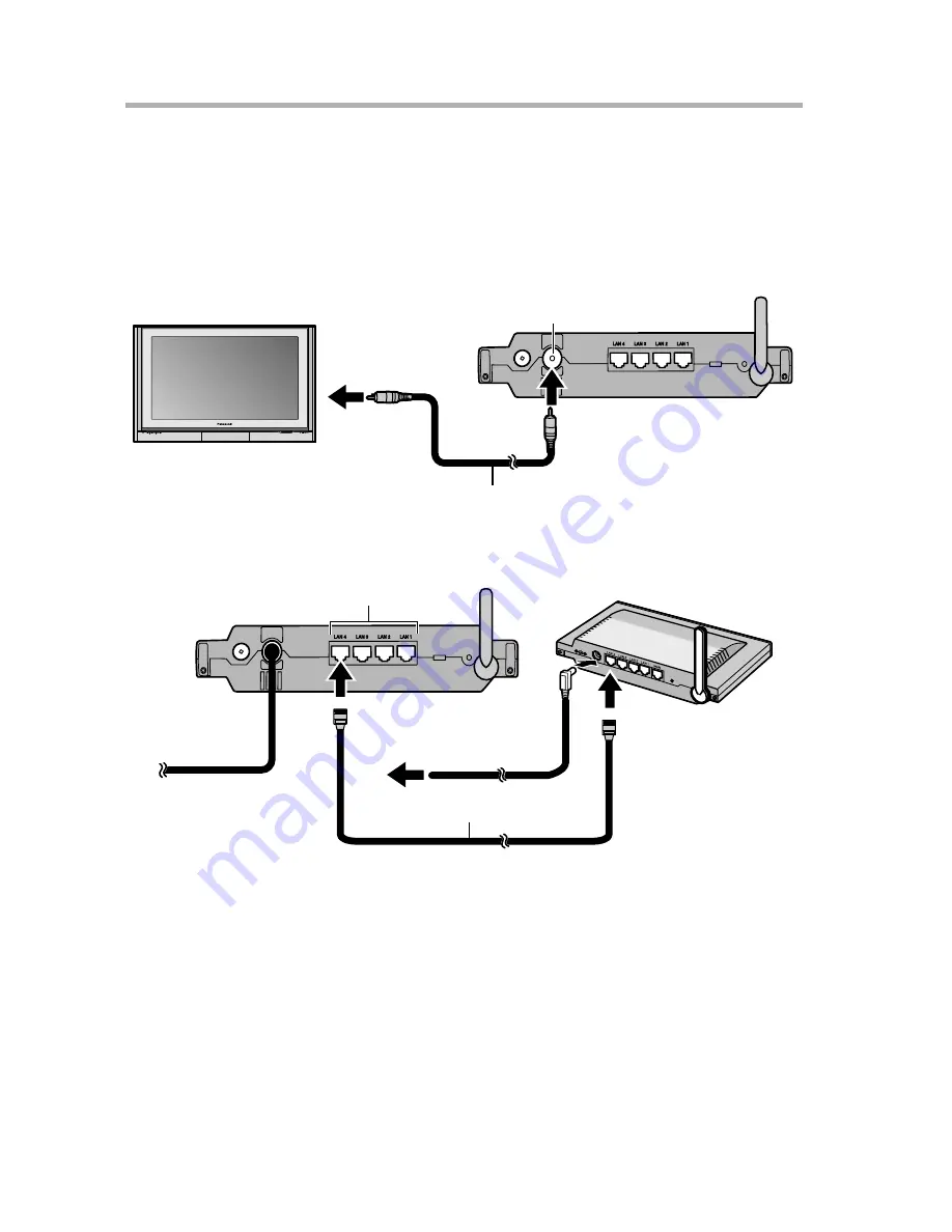
Television and BB-HGW700A Connection
1.
Connect the video cable from the BL-WV10A video output port to the
television’s video input (yellow) jack.
2.
Connect the Ethernet cable supplied with the BB-HGW700A to any of the LAN
jacks on the BL-WV10A and turn on the BB-HGW700A.
•
Turn on all cameras connected to the BB-HGW700A.
3.
Turn on the television.
4.
Switch the television input mode to video.
5.
Confirm that the mode switch on the back of the BL-WV10A is set to [SETUP].
6.
Insert the DC plug from the AC adaptor into the DC IN jack of the BL-WV10A.
•
Make sure 2 minutes have passed since you turned on the BB-HGW700A.
TV
Rear panel of BL-WV10A
Video cable
Video output port
To external
video input
of TV
Rear panel of
BL-WV10A
Rear panel of
BB-HGW700A
To power outlet
(AC 110 V)
Ethernet cable
LAN jacks


