13
SET-UP
NOTE
The Air Hose and Slide Rod must be positioned to
prevent any kinking of the Hose. Kinks in the Hose
will prevent proper air flow when the system is
operated and will cause a deterioration in
performance.
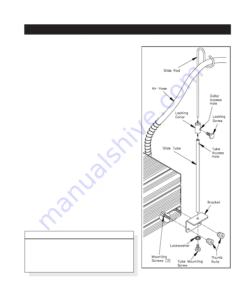
Figure 7.
2. From the rear of the power source, insert the 2 enclosed
Mounting Screws (head first) into the bottom "T" Slot
on the side of the power source case.
3. Place the Bracket onto the side of the power source,
inserting the two (2) Mounting Screws through the two
(2) Mounting Holes in the bracket.
4. Install a Thumb Nut onto end of each Mounting Screw.
5. Adjust Bracket flush with rear of power source.
Tighten Thumb Nuts to secure bracket in position.
6. Position Locking Collar over end of Slide Tube with
beveled end of collar facing up and with Collar Access
Hole in line with Tube Access Hole.
7. Insert end of Slide Rod through top of Locking Collar
and into the Slide Tube. Slide rod fully into the tube.
8. Install the Locking Screw into the Locking Collar.
Ensure that the collar is positioned properly on the
tube; see step #6. Tighten the Locking Screw and
check the Slide Rod; it should now be secured in
position by the Locking Screw.
9. Check to ensure the the Slide Rod can be moved up and
down when the Locking Screw is loosened and secured
in position when the screw is tightened.
10. Place the ThermoFlo handpiece air hose in position as
shown in the loop at the end of the Slide Rod and with
the handpiece in the cubby (or installed on the Work
Platform). The hose and Slide Rod can be easily
adjusted for optimum use.
Содержание PROGRAMMABLE THERMOFLO
Страница 2: ...i MANUAL NO 5050 0420 REV A...
Страница 26: ...21 QUICK START...


