- 184 -
- 185 -
ST
AND UNIT
W
ALL UNIT
SCREEN C
ONFIG'
GRAPHIC C
ONFIG'
FRAME INS
TALL'
SENSOR C
ONFIG'
OPERA
TION
OPERA
TION
2
. PC Bracket Connection
2
.
1
. PC Bracket Connection Diagram
y
PC Bracket controls the power for the e-board and the PC simultaneously as well as RS-
232
C devices.
y
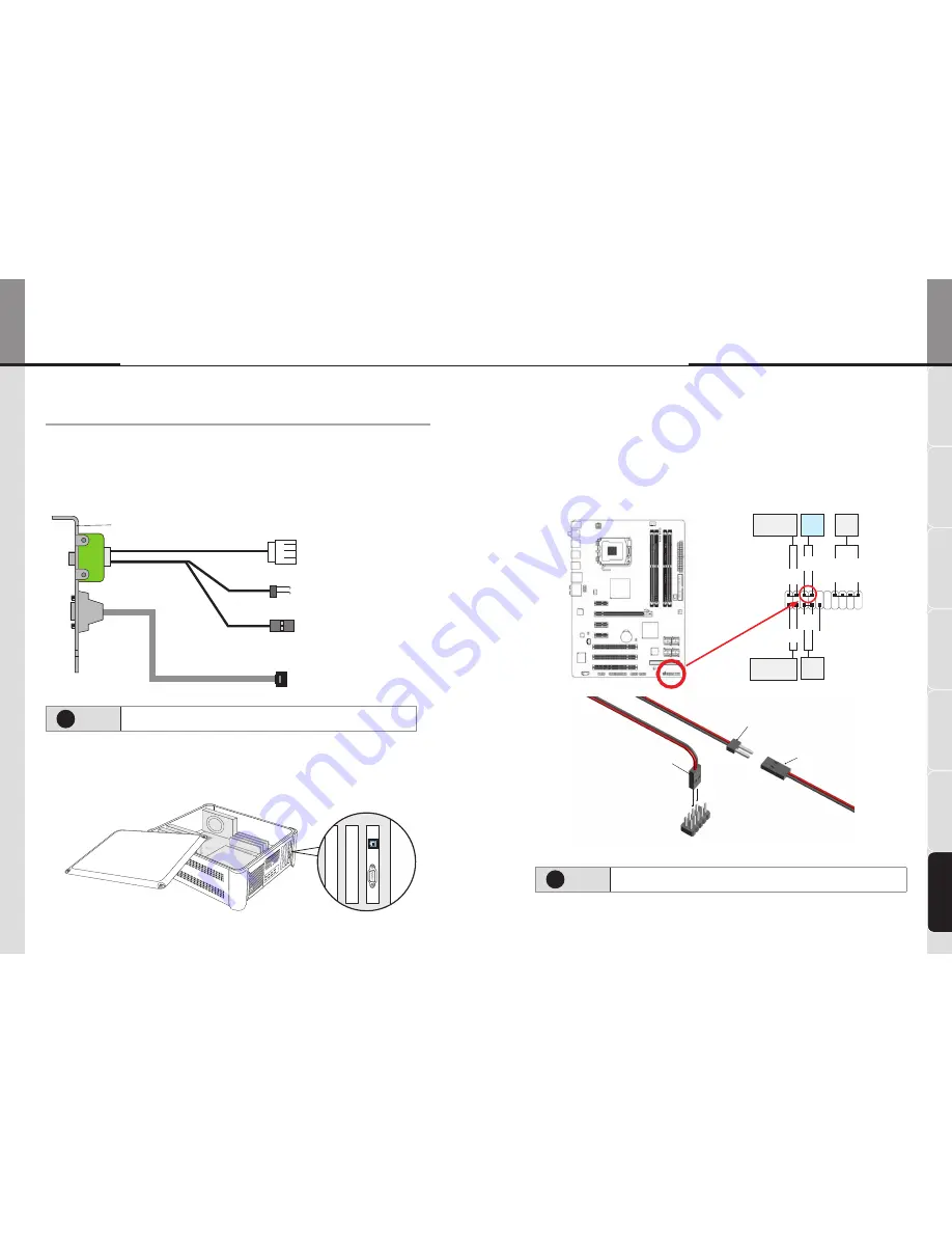
Following is the PC Bracket Connection Diagram.
y
Refer to the instruction of the main board for further information for F_PANEL (Front Panel Header)
PC BRACKET
➍
RS-
232
C Connector
Connect to the RS-
232
C port
in the main board
➊
Power Connector
Connect to Power Supply
➌
Power Switch Connector B
Connect to the power switches
PW+, PW- in the front panel
header of the main board.
➋
Power Switch Connector A
Connect to the power switches
PW+, PW- in the front panel of
the case.
!
Ø
Note
If you purchase the optional PC from ORION, PC Bracket is already installed in
the PC.
2
.
2
. Install PC Bracket
y
Turn off the PC
y
Open the PC cover and install the PC Bracket at the empty slot and screw a bolt to fix.
2
.
3
. Power Switch Connection
y
Put the Power Switch Connector B on the power switches PW+, PW- in the front panel header of the main board.
y
If the power switch in the front panel of the case is connected, disconnect it and connect the Power Switch
Connector B.
y
In that case, connect the power switch connector in the front panel of the case and Power Switch Connector A.
1
19
2
20
NC
HD
-
NS
G-
PW
-
RE
S+
HD
+
NS
G+
PW
+
RE
S-
SP
EA
K+
SP
EA
K-
Message/Power/
Sleep LED
Power
Switch
Speaker
Hard Drive
Activity LED
Reset
Switch
!
Ø
Note
Refer to the instruction of the main board for further information for F_
PANEL (Front Panel Header)
PC BRACKET
Power Switch Connector B
PC BRACKET
Power Switch Connector A
Power Switch Connect
of the case
F_PANEL of the Main Board
OPE-11701
Innovative e-Board of New Conception
e-Board


