NuMicro® NUC029LEE/NUC029SEE
32-bit Arm
®
Cortex
®
-M0 Microcontroller
Aug, 2018
Page
391
of
497
Rev 1.00
N
U
MICRO
®
N
UC02
9L
E
E
/N
UC029
S
E
E
T
E
CHN
ICA
L R
E
F
E
R
E
NC
E
M
A
NU
A
L
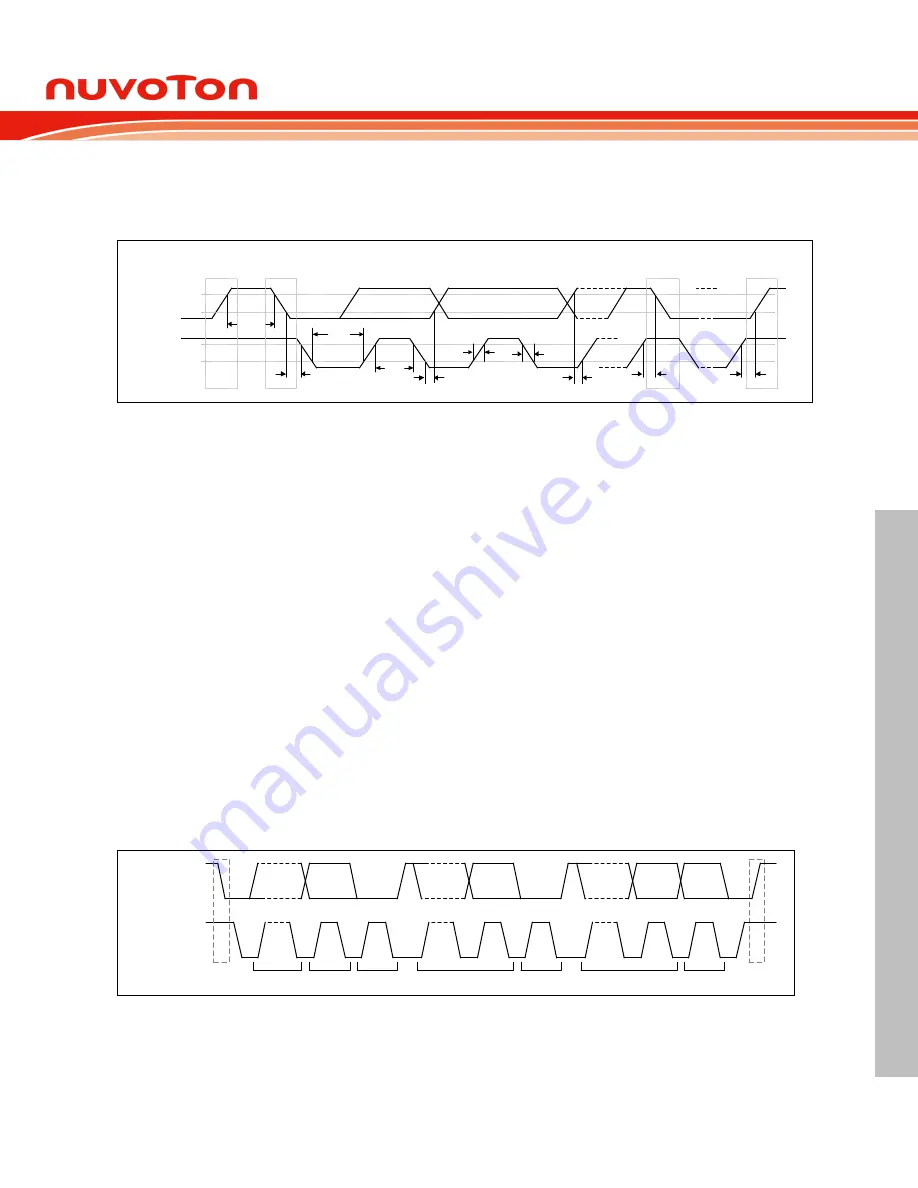
of I2Cn_SCL; therefore, the I2Cn_SDA line may be changed only during the low period of
I2Cn_SCL and must be held stable during the high period of I2Cn_SCL. A transition on the
I2Cn_SDA line while I2Cn_SCL is high is interpreted as a command (START or STOP). Please
refer to the following figure for more detailed I
2
C bus timing.
t
BUF
STOP
I2Cn_SDA
I2Cn_SCL
START
t
HD;STA
t
LOW
t
HD;DAT
t
HIGH
t
f
t
SU;DAT
Repeated
START
t
SU;STA
t
SU;STO
STOP
t
r
Figure 6.14-2 I
2
C Bus Timing
The device’s on-chip I
2
C provides the serial interface that meets the I
2
C bus standard mode
specification. The I
2
C port handles byte transfers autonomously. To enable this port, ENS1
(I2CON[6]) should be set to '1'. The I
2
C hardware interfaces to the I
2
C bus via two pins:
I2Cn_SDA and I2Cn_SCL. When I/O pins are used as I
2
C ports, user must set the pins function to
I
2
C in advance.
Note:
Pull-up resistor is needed for I
2
C operation as the I2Cn_SDA and I2Cn_SCL are open-drain
pins.
6.14.5.1 I
2
C Protocol
The following figure shows the typical I
2
C protocol. Normally, a standard communication consists
of four parts:
START or Repeated START signal generation
Slave address and R/W bit transfer
Data transfer
STOP signal generation
I2Cn_SDA
I2Cn_SCL
1-7
8
9
S
1-7
8
9
1-7
8
9
P
ADDRESS
W/R
ACK
DATA
ACK
DATA
ACK
Figure 6.14-3 I
2
C Protocol
6.14.5.1.1
START or Repeated START signal
When the bus is free or idle, meaning no master device is engaging the bus (both I2Cn_SCL and
I2Cn_SDA lines are high), a master can initiate a transfer by sending a START signal. A START
signal, usually re
ferred to as the “S” bit, is defined as a HIGH to LOW transition on the I2Cn_SDA


