background image

59

www.climacoolcorp.com

Copper Tubing, Brazing and System 


Reprocessing Recommendations

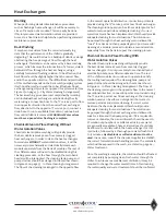
Copper tubing must be refrigeration grade (ACR type 

“L”). Be sure to install appropriate copper fittings rated 

for ACR applications . Never leave refrigerant lines open 

when they are not directly being installed . Never rely on 

the last refrigerant connection joint at a specific section 

(UCR module or condenser section) to provide structural 

support for the interconnecting piping . Line pulsation may 

occur at start-up and shut down of scroll compressors . 

Additional line support may be required to prevent vibration 

transmission or movement in the line . Ensure that all 

interconnecting piping is properly and independently braced 

at 7 feet minimum intervals, and within 2 feet from each 

section’s final connection location, to prevent joint fracture 

due to line vibrations or liquid hammering .

Use 15% silver-phosphorus braze filler rod when brazing 

copper-to-copper joints . When brazing copper-to-brass 

joints, apply “sta-silv” brazing paste (or equivalent) 

sparingly to the joint areas, and use 45% silver-phosphorus 

braze filler rod. Always purge a generous flow of dry 

nitrogen (approximately 10 CFH) through the lines while 

brazing to prevent internal scaling of copper oxide on 

heated copper surfaces exposed to air .

When sizing the interconnecting refrigerant lines, never 

use the stub-out sizes at the UCR module section as the 

determining factor . For proper operation, all discharge 

and liquid lines must be sized in accordance with the 

recommendations provided in the following piping sections . 

After installing the interconnecting piping, proper system 

evacuation and reprocessing guidelines are provided in 

the Refrigeration System Reprocessing section of the Split 

System Interconnecting Piping on page 60 .

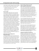
Liquid Line Piping Recommendations 

All liquid lines should be kept as short as possible, and the 

line sizing is determined to provide for a low-pressure drop 

to prevent liquid line flashing. There should always be a 

gradual negative elevation change when traversing from 

the remote condenser location to the UCR module section . 

Avoid any reversing elevation changes throughout this liquid 

line run . Horizontal liquid lines should be sloped downward 

in the direction of refrigerant flow at a pitch of 1/8” per foot. 

The total equivalent distance between the condenser and 

the UCR section (including allowances for U-bends and 90° 

elbows) should not exceed 100 feet . Avoid  routing liquid lines 

through heated spaces which may result in undesirable flash 

gas generated at the TXV inlet . Avoid insulating liquid lines .

Conforming to local and national codes is the responsibility 

of the service technician or installing contractor . The service 

technician should be familiar with the following codes:

• 

ASHRAE Standard Safety Code for Mechanical 

Refrigeration, ANSI/ASHRAE 15-1978

• 

American National Standard Code for Pressure Piping, 

ANSI B31 .5-1974

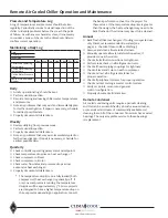
Factory Tested  

ClimaCool modular chillers have been pressure-tested, 

evacuated and both refrigeration circuits pressurized 

with 50 psig of dry nitrogen prior to shipment . The split 

system chillers require interconnecting refrigeration piping 

between the ClimaCool UCR modular remote air cooled 

chiller and the remote condenser section . The condenser 

section provided by ClimaCool is typically a remote air-

cooled condenser configuration. Contact the factory for 

guidelines for customer supplied, field integration to other 

permissible condenser types, such as evaporative condenser 

configurations. The refrigerant charge will be weighed-

in in the field based on the condenser configuration and 

condenser model . The ClimaCool UCR030 model is equipped 

with a 72 pound liquid receiver capacity per compressor 

circuit . The UCR050 and UCR070 models have an 84 pound 

liquid receiver installed per circuit . All ClimaCool UCR models 

MUST be charged with R-410A refrigerant . Field installation 

of additional receiver capacity may be required depending 

on the refrigerant retaining volume of the remote 

condenser and interconnecting piping . After the total 

refrigerant amount is charged into each circuit (weighed 

in using an appropriate refrigeration scale), the resulting 

weight should be recorded on the UCR module data plate 

for future reference . See Refrigerant Charging Procedure 

on pages 61 - 62 for specific charging guidelines. Also 

refer to the job specific submittal data for the appropriate 

refrigerant charge amount .

UCR Modular Chiller Refrigeration  

Piping Connections

The discharge and liquid line stub-out connections at the 

UCR module section are equipped with shut-off valves with 

capped leads . Never uncap these leads without checking 

the shutoff valves to be sure that they are fully closed and 

the units are ready for piping . All scroll compressors in 

ClimaCool UCR modules are equipped with POE refrigeration 

oil . Systems with compressors using POE oils must be kept 

closed at all times except when the interconnecting piping is 

being directly installed . POE oils are extremely hygroscopic 

in nature and will absorb an undesirable amount of moisture 

from normal ambient air within a few minutes .

Refrigeration System Re-Processing 

Содержание CLIMACOOL UCR 30

Страница 1: ...Remote Air Cooled Modular Chillers Model UCR 30 50 and 70 tons Installation Operation Maintenance Manual...

Страница 2: ...9 Power Distribution Drawing 30 Remote Condenser 31 32 Head Pressure Control Valve Operation LAC 10 33 37 Remote Condenser Installation 38 45 Pre Startup 46 Pre Startup Checklist 47 Startup 48 49 Subc...

Страница 3: ...l un des trois l ments mentionn s ci dessus sont remplies changer deux des trois lignes lectriques alimen tant la interrupteur de s curit et v rifier la rotation du compresseur WARNING ADVERTISSEMENT...

Страница 4: ...s Tous les capteurs de pression doivent tre retir s avant l vacuation ou de test d unit de pression Faute de quoi se traduira par des dommages des capteurs WARNING ADVERTISSEMENT For field installatio...

Страница 5: ...ooved couplings and mounting hardware kits are on site prior to connecting the modules Note Consult factory for handling other than in the upright position Rigging and Lifting Each module should be li...

Страница 6: ...5 NOMINAL TONS 030 050 070 DESIGN SERIES A VOLTAGE F 460 3 60 H 208 230 3 60 N 575 03 60 CONTROLS ELECTRICAL A Standard DDC COMPRESSOR TYPE S Scroll MODEL CONFIGURATION S Standard REJECTION OPTIONS 0...

Страница 7: ...6 6 Notes 1 Unit tonnage ARI rating conditions 44 F leaving chilled water temperature and 2 4 GPM per ton through the evaporator 95 F entering condenser air temperature dry bulb 30 F condenser TD and...

Страница 8: ...n Motor Hp ea 1 0 hp 1 0 hp 1 0 hp Quantity of Fan Motors 4 4 4 kW Input ea Fan Motor I Total kW Input for All Motors 1 1 I 4 4 1 1 I 4 4 1 1 I 4 4 FLA per Fan Motor 460V 3 60 I Total FLA 460V 3 60 2...

Страница 9: ...Fan Motor Hp ea 1 0 hp 1 0 hp 1 0 hp Quantity of Fan Motors 4 6 6 kW Input ea Fan Motor I Total kW Input for All Motors 1 1 I 4 4 1 1 I 6 6 1 1 I 6 6 FLA per Fan Motor 460V 3 60 I Total FLA 460V 3 60...

Страница 10: ...RPM db 10 46 5 I 73 1 46 5 I 73 1 46 5 I 73 1 Dimensions W x L x H Inches 88 X 127 X 49 88 X 127 X 49 88 X 127 X 49 Net Weight I Shipping Weight lbs 1290 I 1510 1290 I 1510 1390 I 1610 Remote Condense...

Страница 11: ...ection Size Inches Unit Weight1 Pounds Operating Weight2 Pounds 030 208 230 460 575 3 60 337 8 651 8 34 1 4 41 1 4 27 1 2 58 47 1 2 55 1 2 6 1170 1265 050 208 230 460 575 3 60 337 8 651 8 34 1 4 41 1...

Страница 12: ...e to the unit may occur Figure 5 Lifting and Transporting Modules Pallet jacks or fork lifts are required for lifting and transporting the module Each module has base cutouts provided for ease of mane...

Страница 13: ...e determined by a qualified structural engineer per individual job requirements ClimaCool recommends locking down the chiller to a concrete base or to three 3 4 base mounting rails using the six 6 bol...

Страница 14: ...anels and 30 clearance for rear access to modules 2 Allow a minimum of 18 height clearance for service 3 Local building or electrical codes may require additional clearance Consult applicable codes To...

Страница 15: ...hiller from the structure is recommended by installing vibration eliminating springs or pads under the base rails on which the chiller will rest see page 10 Mounting Rail and Vibration Isolation One e...

Страница 16: ...he installing contractor Sound Attenuation Panels and Gasket Attenuation panels are enclosures made of 18 gauge galvanized steel with powder coat paint finish and fiberglass insulation Field Installed...

Страница 17: ...be reversed by opening the main electrical disconnect and switching any two of the main power supply leads feeding that compressor s contactor Proper Voltage Balance Occasionally in three phase circu...

Страница 18: ...0 254 mm wall 0 144 in 3 6576 mm O D DC resistance 15 2 Ohms 1000 feet 50 Ohms km nominal Capacitance 12 5 pF ft 41 pF meter nominal conductor to conductor Characteristic impedance 100 Ohms nominal We...

Страница 19: ...17 www climacoolcorp com Voltage Phase Monitor Wiring Diagram...

Страница 20: ...em for a total of four 4 taps If a port is shared by the pressure differential flow sensor and the pressure gauge it will require two 2 1 2 taps See Water Piping Configurations page 20 Water Isolation...

Страница 21: ...f ClimaCool sensors and controls for control of field supplied bypasses or other field supplied items The recommended method is to control via differential pressure or gpm flow meters across the chill...

Страница 22: ...awings 5 A pressure differential flow sensor is a required safety device for ClimaCool modular chillers on the chilled water circuits 6 A strainer with a minimum of 60 mesh stainless steel screen is a...

Страница 23: ...te s Ports Heat Exchanger Leaving Chilled Water Temperature Sensor Refrigerant Circuit 1 Refrigerant Circuit 2 Hydronic Refrigeration Figure 15 Chilled Water Circuit Note Figure 15 depicts hydronic pi...

Страница 24: ...mpact exchangers are true dual circuit heat exchangers in which each water channel is anked by two refrigerant circuits This design gives maximum performance even at part load Of course full performan...

Страница 25: ...stem The following method is recommended to properly clean the water systems 1 Before cleaning the system install a temporary bypass line between the main supply and return water headers of both chill...

Страница 26: ...recommended to install an intermediate plate and frame heat exchanger to isolate the ClimaCool chiller from the building water system Cooling Tower The cooling tower should be located away from source...

Страница 27: ...ed of special controls or glycol additives Leaving water temperatures below 40 F can result in evaporator suction temperatures below the freezing point of water Therefore a glycol solution additive is...

Страница 28: ...mum Entering Condenser Air Temperature 20FTD F 120 120 120 Maximum Entering Condenser Air Temperature 30FTD F 110 110 110 Minimum Condenser Temperature Differential TD F 20 20 20 Maximum Condenser Tem...

Страница 29: ...27 www climacoolcorp com Evaporator Water Pressure Drop Charts...

Страница 30: ...28 www climacoolcorp com Glycol Performance Adjustments Factor Charts...

Страница 31: ...kW Power Multplier Capacity Multplier Flow gpm Multplier kW Power Multplier Capacity Multplier Flow gpm Multplier kW Power Multplier Capacity Multplier Flow gpm Multplier kW Power Multplier 8 1 00 1...

Страница 32: ...hielded cable daisy chain from the master controller to the modules see Figure 18 Figure 17 Specifications for ARC156 Wiring Description Single twisted pair low capacitance CL2P TC foam FEP plenum rat...

Страница 33: ...ow and access all sides of the unit should be a minimum of W away from any wall or obstruction It is preferred that this distance be increased whenever possible Care should be taken to see that ample...

Страница 34: ...nal 20 F Variable speed control furnished for lead fans Mechanical head pressure fan cycling control provided for on all others Optional 20 F Factory furnished field installed LAC 10 flooded head pres...

Страница 35: ...hot gas raises liquid pressure in the receiver allowing the system to operate normally Figure 23 LAC 10 Valve Operation The valve designation LAC stands for Low Ambient Control The LAC 10 is a three w...

Страница 36: ...od the condenser coil at the appropriate ambient The factors involved in calculating the extra pounds of refrigerant are 1 Length of tubing and return bends in condenser 2 Minimum ambient temperature...

Страница 37: ...80 0 0 0 0 70 0 0 0 0 60 26 20 10 4 50 45 40 33 28 40 56 42 46 42 30 64 60 55 51 20 69 66 62 59 0 76 73 70 68 20 80 79 76 73 Refrigerant Charging Procedures for Head Pressure Control Valve Once the am...

Страница 38: ...nt will be backed up into the condenser and the sight glass will indicate bubbles in the liquid line 3 Add more refrigerant while allowing sufficient time for the refrigerant to stabilize and clear th...

Страница 39: ...AC Discharge line to LAC restricted Remove restriction in fitting s or line Malfunction High Head Pressure Chart Possible Cause Remedy Dirty condenser coil Clean coil Air on condenser blocked off Clea...

Страница 40: ...35 TON CIRCUIT W HOT GAS BYPASS 1 1 8 1 1 8 1 5 8 1 1 8 REF UCR070 42 1 2 TON CIRCUIT W OUT HOT GAS BYPASS NOT 2 1 8 2 1 8 1 3 8 REF UCR085 USED 42 1 2 TON CIRCUIT W HOT GAS BYPASS 1 3 8 1 3 8 1 5 8 1...

Страница 41: ...39 www climacoolcorp com Condenser Layout for RC1 007A H24 and RC1 008A H24 1 Row 2 Fan 1140RPM...

Страница 42: ...40 www climacoolcorp com Condenser Layout for RC2 019A 026A and 31A H48 and RC2 038A H44 2 Row 4 Fan 1140RPM...

Страница 43: ...41 www climacoolcorp com Condenser Layout for RC2 018A X48 RC2 026A X40 and RC2 032A X44 2 Row 4 Fan 830 RPM...

Страница 44: ...42 www climacoolcorp com Condenser Layout for RC2 014A Q48 RC2 017A Q42 RC2 021A Q48 and RC2 025A Q44 2 Row 4 Fan 540 RPM...

Страница 45: ...43 www climacoolcorp com Condenser Layout for RC2 020A V48 RC2 025A V42 RC2 033A V42 and RC2 038A V42 2 Row 4 Fan Variable Speed...

Страница 46: ...44 www climacoolcorp com Condenser Layout for RC2 047A H62 RC2 046A V60 RC2 032A Q62 RC2 039A Q64 RC2 039A X60 and RC2 047A X62 2 Row 6 Fan...

Страница 47: ...45 www climacoolcorp com 45 www climacoolcorp com Condenser Layout for RC2 048A Q82 2 Row 8 Fan 540RPM...

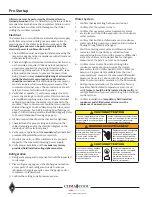
Страница 48: ...lace refrigerant gauges on the discharge and suction access ports of each refrigerant circuit to ensure a refrigerant charge is present Leave the gauges on for compressor rotation check 3 Confirm the...

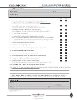
Страница 49: ...lled and wired to the CoolLogic controller 7 Have all chiller coupling connections been leak tested 8 Is water presently circulating through chiller 9 Veri ed that temperature sensors and voltage phas...

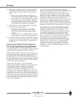
Страница 50: ...0 psid 10 Confirm the jumper locations for all master controller and module controllers as shown on the wiring diagrams provided on the inside electrical door panels Set the rotary switches for the MA...

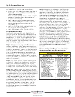
Страница 51: ...temperature The saturated condensing temperature is found by converting the liquid line pressure reading on the manifold gauge to the related temperature The normal subcooling temperature range at the...

Страница 52: ...ersion of the startup forms are available on www climacoolcorp com in the Service page Water Testing Extract three water samples from each water loop Hot Water Condenser Chilled Water Evaporator using...

Страница 53: ...it is usually safe to allow the compressor to run Step 4 After starting the compressor listen for unusual sounds such as knocking If heard immediately stop the compressor Do not restart until the pro...

Страница 54: ...re Verify Safety Setting Limits Low Temp High Pressure Low Pressure Rep Signature Print Name E Signature Check Box Authorized Signature All wiring terminations in module panel safeties and compressors...

Страница 55: ...er is located Less than 30 feet Higher Eleva on relative to chiller module 5 Refrigerant Piping Geometry to Remote A C Condenser Horizontal Distance A C Condenser is located at an aggregate total dist...

Страница 56: ...l data taken The temperature drop rise on a fully loaded both compressors heat exchanger is generally 10 F If only one compressor is running the temperature drop rise will be approximately 5 F Some pr...

Страница 57: ...he flow of the cleaning is arranged in the opposite flow to the normal operational direction Connection points are provided using the 3 4 service ports at each heat exchanger The cleaning solution use...

Страница 58: ...cuit Service Port 3 4 Refrigerant Circuit Header Header To Cooling Tower From Cooling Tower Cleaning Tank Cleaning Pump Pete s Ports Isolation Ball Valves 2 2 or 3 Heat Exchanger Figure 2 In Place Cle...

Страница 59: ...acuum A suitable hydraulic pump should be used to add oil and reserved for this process It is imperative that oil type be verified prior to adding to a compressor Oil should only be added to a compres...

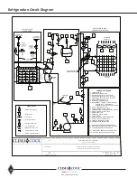
Страница 60: ...QUID RECEIVER 14 PRESSURE RELIEF VALVE 15 FILTER DRIER 16 SIGHT GLASS MOISTURE INDICATOR 17 LIQUID LINE SOLENOID VALVE 18 THERMAL EXPANSION VALVE 19 CHILLER EVAPORATOR BPHX S1 DISCHARGE TEMPERATURE SE...

Страница 61: ...ough heated spaces which may result in undesirable flash gas generated at the TXV inlet Avoid insulating liquid lines Conforming to local and national codes is the responsibility of the service techni...

Страница 62: ...tion and potentially cause nuisance head pressure trips Moisture in the system can cause chemical reactions with many POE oil additives resulting in the formation of undesirable acids which corrode th...

Страница 63: ...refrigerant cylinder tank pressures have equalized it will be necessary to finish the refrigerant charging process by gradually metering small bursts of liquid refrigerant into the suction line of the...

Страница 64: ...40 100 80 9 25F 1140 100 87 9 20F 1140 100 94 9 45F 1140 125 119 1 25F 1140 125 122 2 20F 1140 125 125 2 45F 1140 150 130 8 25F 1140 150 133 8 20F 1140 150 136 9 Model Minimum Outdoor Temp Condenser F...

Страница 65: ...ulation shall be provided on suction side refrigerant tubing including refrigerant to chiller heat exchanger to prevent condensation Compressors Each module shall contain two scroll compressors indepe...

Страница 66: ...itor and report the following system parameters for the chiller system Chilled water entering and leaving temperature Evaporator water flow availability Any module failure condition shall cause a faul...

Страница 67: ...ts Factory installed water isolation valves and flush ports shall provide isolation to the module for maintenance and cleaning of evaporator heat exchangers while adjacent modules continue normal oper...

Страница 68: ...elow for the strainer installation 1 The carbon steel CS strainer should be placed on a firm supporting surface Failure to do so can cause stress on the weld joints It is recommended a concrete pad be...

Страница 69: ...sure differential reaches 5 10 psi the strainer element may require cleaning Caution Prior to dismantling the strainer for cleaning it is imperative that the strainer assembly is isolated and complete...

Страница 70: ...tor fitted with a suitable pressure relief valve strategically located within the water system may provide adequate protection against the effects from water hammer Careful attention should be given t...

Страница 71: ...n the moving parts The electric motor supplied a sufficient amount of power to cause personal injury Take precaution when handling Water Resistance The valve and controller are water resistant but not...

Страница 72: ...matic inside the PDA box by removing the four screws on the cover plate Water Resistance The Pressure Differential Alarm Controller is water resistant but not water proof Do not install below ground l...

Страница 73: ...if provided 2 WYE strainers must be positioned in the pipeline ahead of the equipment requiring protection 3 To provide for easier maintenance the WYE strainer should be located where the drain plug...

Страница 74: ...odically checking for leaks During normal use the screen will become clogged with foreign matter causing the differential pressure to increase Once the differential pressure has increased to an unacce...

Страница 75: ...to place using slings positioned underneath the inlet and outlet connections 4 Install a standard ANSI 1 8 thick flange gasket between the basket strainer and pipeline flanges on both sides Install lu...

Страница 76: ...ay to determine when the screen needs to be replaced is to install pressure gauges on the inlet and outlet sides of the strainer The maximum acceptable pressure drop across the strainer will indicate...

Страница 77: ...R070AFASAC00S 575V 3PH 60HZ 89 100 125 125 150 44 5 55 7 239 100 70 Notes 1 RLA Rated Load Amps are calculated as per UL1995 2 MCA Minimum Circuit Ampacity is 125 of the RLA of the largest compressor...

Страница 78: ...76 www climacoolcorp com Wiring Diagram...

Страница 79: ...77 www climacoolcorp com Wiring Diagram...

Страница 80: ...78 www climacoolcorp com Wiring Diagram CoolLogic Control Panel...

Страница 81: ...79 www climacoolcorp com Wiring Diagram CoolLogic Control Panel...

Страница 82: ...azed plate heat exchanger Clean in place heat exchanger as described on page 54 Improper chilled water circulation Use an ample sized cleanable strainer in the chilled water circuit make certain the s...

Страница 83: ...damages due to freezing of the water supply an inadequate or interrupted water supply corrosives or abrasives in the water supply or improper or inadequate ltration or treatment of the water or air s...

Страница 84: ...es but are merely ClimaCool s opinion or commendation of its products USGBC and related logo is a trademark owned by the U S Green Building Council and is used with permission Modbus is a registered t...

Отзывы: