14
www.climacoolcorp.com
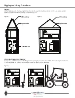
Unit Installation
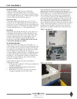
Inspect the pipe ends to ensure they are free from any
indentations, projections, roll marks or other harmful
surface defects such as loose paint, scale, dirt, chips,
grease and rust . Inspect the grooved coupling gasket for
any defects . Apply a thin layer of silicone or other non-
petroleum lubricant to the sealing lips of the gasket as well
as to the exterior of the gasket . Install gaskets on the pipe
ends of one of the two modules to be mated .
Be sure the
gasket is completely on the pipe to avoid damage in the
next step.
Move the second module into position and line
up the piping . Ensure the operator is maintaining alignment
for any additional modules to be added . When pipe ends
are aligned, slide the gasket over the ends and center it
between the grooves . No part of the gasket should protrude
into the groove of either pipe end . Place the coupling halves
over the gasket and make sure that the coupling keys
(the part that goes into the groove) are engaged into the
grooves . Insert the bolts and install nuts to hand tighten .
Ensure the oval neck of the bolt engages into the bolt hole
of the housing .
Tighten nuts alternately and equally until
the bolt pads meet and make metal to metal contact.
Tighten nuts by another quarter to half turn to make sure
the nuts and bolts are snug and secure . The use of a torque
wrench is usually not required .
Uneven tightening of bolts
may cause the gasket to be pinched resulting in immediate
or delayed leaks.
Header Insulation
Chilled water piping is pre-insulated on each module
at the factory with 3/4” closed cell insulation. After
bolting all modules together and leak testing, the entire
coupling connection will need to be insulated by the
installing contractor .
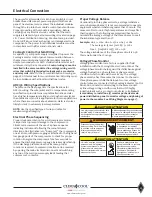
Sound Attenuation Panels and Gasket
Attenuation panels are enclosures made of 18 gauge
galvanized steel with powder coat paint finish and fiberglass
insulation . Field Installed panel package includes one (1)
upper panel made out of two (2) sections and one (1) lower
panel for each side of bank (field installed), four (4) panels
for each module in the bank (factory installed) and gasket
sealant tape for installation between modules . Install panels
by setting in place and locking down with the half turn
latches or self tapping screws .
Note: Panel package includes
a compressed 1” x 1” gasket sealant tape for installation
between modules
.
Install the tape on the outer frame on
the side of one module prior to installing the adjacent
modules.
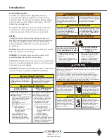
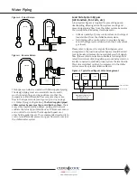
CAUTION/ATTENTION
3 PHASE SCROLL
COMPRESSOR UNIT
UNITÉ COMPRESSEUR
SCROLL 3-PHASE
If this unit uses a 3 Phase Scroll
Compressor, the following instructions
MUST BE
followed:
• Unit power supply
MUST BE
wired
in the proper sequence to avoid
damage to the 3 Phase Scroll
Compressor;
• Scroll Compressors with
INCORRECT
rotation show the
following characteristics:
- High sound level;
- High suction pressure and low
discharge pressure;
- Low current draw.
• If any of the three above
characteristsics exist, swap
two of the three supply wires
at the disconnect and recheck
compressor for incorrect rotation.
Si cet appareil utilise compresseur
scroll 3-Phase, les instructions
suivantes doivent être suivies:
• L’alimentation de l’appareil doit
être monté dans l’ordre correct
pour éviter endommager le
compresseur scroll 3-Phase;
• Compressuers scroll avec
rotation incorrecte montrent les
caractéristiques suivantes:
- Haut niveau de son;
- Pression d-aspiration élevée
et une faible pression de
décharge;
- Faible ampérage.
• Si l’un des trois éléments
mentionnés ci-dessus sont
remplies, échanger deux des trois
lignes électriques alimen tant la
interrupteur de sécurité et vérifier
la rotation du compresseur.
Содержание CLIMACOOL UCR 30
Страница 19: ...17 www climacoolcorp com Voltage Phase Monitor Wiring Diagram...
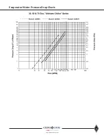
Страница 29: ...27 www climacoolcorp com Evaporator Water Pressure Drop Charts...
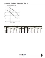
Страница 30: ...28 www climacoolcorp com Glycol Performance Adjustments Factor Charts...
Страница 41: ...39 www climacoolcorp com Condenser Layout for RC1 007A H24 and RC1 008A H24 1 Row 2 Fan 1140RPM...
Страница 42: ...40 www climacoolcorp com Condenser Layout for RC2 019A 026A and 31A H48 and RC2 038A H44 2 Row 4 Fan 1140RPM...
Страница 43: ...41 www climacoolcorp com Condenser Layout for RC2 018A X48 RC2 026A X40 and RC2 032A X44 2 Row 4 Fan 830 RPM...
Страница 47: ...45 www climacoolcorp com 45 www climacoolcorp com Condenser Layout for RC2 048A Q82 2 Row 8 Fan 540RPM...
Страница 78: ...76 www climacoolcorp com Wiring Diagram...
Страница 79: ...77 www climacoolcorp com Wiring Diagram...
Страница 80: ...78 www climacoolcorp com Wiring Diagram CoolLogic Control Panel...
Страница 81: ...79 www climacoolcorp com Wiring Diagram CoolLogic Control Panel...


