49
www.climacoolcorp.com
18 .
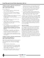
Verify proper communications from each module back
to the master controller using the “STATUS” menu,
then indexing down to the desired compressor data
screen .
• If the compressor data parameters all read “0,”
then communications are not yet established, and
communications cable troubleshooting is required .
• When all compressor data parameters read actual
values which agree with the refrigerant gauge set
and refrigerant line temperatures, then it is safe to
assume that communications are established .
19 .
Set up the master controller parameters according to
the specific job submittal sheets.
• All parameters can be found in the FN 2 menu
(setup), FN 6 menu (module factory settings),
FN 7 menu (service), FN 8 menu (master factory
settings) .
• It is imperative to access EVERY MENU and EVERY
PARAMETER to ensure all settings are appropriate .
20 .
Set up the Building Automation System (BAS) interface
parameters (as required) using the FN 0 menu (network
number selection, IP addressing), FN 4 menu (device
instances) .
Adjusting Unit Charge and Thermal Expansion
Valves Using Subcooling and Superheat Method
Due to varying installation conditions/applications and to
optimize performance, proper refrigerant charge and thermal
expansion valve (TXV) adjustment must be confirmed.
After checking compressor rotation, choose a circuit to be
tested first. Connect test equipment to monitor the suction
line and liquid line temperatures simultaneously . Place a
manifold gauge set on the suction line and liquid line then
start the compressor . As long as the suction pressure is high
enough to prevent the low pressure switch from tripping,
run the compressor for five minutes.
Verify proper subcooling . This is accomplished by
subtracting the liquid line temperature from the saturated
condensing temperature . The saturated condensing
temperature is found by converting the liquid line
pressure reading on the manifold gauge to the related
temperature . The normal subcooling temperature range at
the condenser is 5-15°F, BUT for total accuracy, follow the
charge recommendations found in the selection program . If
subcooling is too low, then refrigerant must be added to the
system. Add charge and wait five minutes before checking
results . If subcooling is too high, then refrigerant must be
removed from the system .
Verify proper superheat by subtracting the saturated
evaporative temperature from the suction line temperature .
The saturated evaporative temperature is found by
converting the suction pressure reading on the manifold
gauge to the related temperature . The proper superheat
temperature range is 6-18°F at normal operating conditions
(typically 44oF leaving chilled water temperature) . If
superheat is low, this may indicate that the expansion valve
is overfeeding . To adjust the expansion valves, turn the
adjustment stem clockwise . This will cause the superheat
to rise. Wait five minutes before checking the results of this
adjustment . Repeat until the desired superheat is achieved .
Once adjusted, also check the discharge gas superheat
(DGSH) to confirm reading is not less than 50°F and the
discharge line temperature is not more that 220°F . To
check discharge gas superheat, first obtain the saturated
condensing temperature by converting the discharge
pressure to saturated refrigerant temperature using a
pressure temperature chart . Next, measure the discharge
line temperature 6 to 10 inches from the compressor .
Subtract the saturated condensing temperature from
the discharge line temperature to find the discharge gas
superheat . If the DGSH is below 50°F, liquid refrigerant
is still present in the suction gas vapor returning to the
compressor . The TXV will require additional clockwise
adjustment to raise the discharge gas superheat into the
acceptable range .
Startup
Содержание CLIMACOOL UCR 30
Страница 19: ...17 www climacoolcorp com Voltage Phase Monitor Wiring Diagram...
Страница 29: ...27 www climacoolcorp com Evaporator Water Pressure Drop Charts...
Страница 30: ...28 www climacoolcorp com Glycol Performance Adjustments Factor Charts...
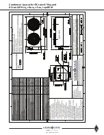
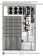
Страница 41: ...39 www climacoolcorp com Condenser Layout for RC1 007A H24 and RC1 008A H24 1 Row 2 Fan 1140RPM...
Страница 42: ...40 www climacoolcorp com Condenser Layout for RC2 019A 026A and 31A H48 and RC2 038A H44 2 Row 4 Fan 1140RPM...
Страница 43: ...41 www climacoolcorp com Condenser Layout for RC2 018A X48 RC2 026A X40 and RC2 032A X44 2 Row 4 Fan 830 RPM...
Страница 47: ...45 www climacoolcorp com 45 www climacoolcorp com Condenser Layout for RC2 048A Q82 2 Row 8 Fan 540RPM...
Страница 78: ...76 www climacoolcorp com Wiring Diagram...
Страница 79: ...77 www climacoolcorp com Wiring Diagram...
Страница 80: ...78 www climacoolcorp com Wiring Diagram CoolLogic Control Panel...
Страница 81: ...79 www climacoolcorp com Wiring Diagram CoolLogic Control Panel...


