35
www.climacoolcorp.com
Head Pressure Control Valve Operation (LAC-10)
since as the compressor unloads, the condenser’s capacity increases and additional flooding is required. Using the same
roof mounted remote condenser as in the earlier example (40°F evaporator and minus 20°F minimum ambient), a multiplier
of .79 is shown in Table 8. And since there is hot gas bypass (50%), this .79 is used to enter Table 10 to find a multiplier of .91.
This final multiplier is applied to the 119 pounds calculated earlier to arrive at the final extra charge requirement: 119 x .91 =
108 pounds . This is added to the normal system charge to arrive at a total system charge .
Table 8
Refrigerant
Minimum
Ambient
°F
Equivalent Length Of Tubing for
Each Return Bend
Density Factor - Pounds Per Foot Of Tubing
Tubing O.D. and Wall Thickness (Inches)
3/8”
(0.016)
1/2”
(0.017)
5/8”
(0.018)
0.875
(0.045)
1.125
(0.05)
1.375
(0.055)
3/8”
1/2”
5/8”
R-410A
-40
0.2
0.25
0.3
0.05
0.10
0.16
0.28
0.47
0.72
-20
0.05
0.10
0.15
0.27
0.46
0.70
0
0.05
0.09
0.15
0.26
0.45
0.68
20
0.05
0.09
0.14
0.25
0.43
0.66
40
0.05
0.09
0.14
0.24
0.41
0.63
60
0.04
0.08
0.13
0.23
0.39
0.60
70
0.04
0.08
0.13
0.23
0.39
0.59
Table 9
Condenser
Ambient
Temperature
°F
Percent of Condenser to be Flooded
High Suction Temperature A/C Chillers
Evaporating Temperature °F
35
40
45
50
80
0
0
0
0
70
0
0
0
0
60
26
20
10
4
50
45
40
33
28
40
56
42
46
42
30
64
60
55
51
20
69
66
62
59
0
76
73
70
68
-20
80
79
76
73
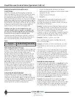
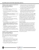
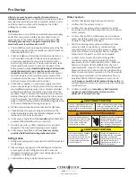
Refrigerant Charging Procedures for Head
Pressure Control Valve
Once the amount of extra refrigerant charge is calculated,
care must be taken in charging the system to ensure
the proper total amount of refrigerant getting into the
system . This is especially true if the ambient temperature
is below 70°F and the liquid drain valve (LAC) is throttling
the refrigerant flow from the condenser. A step by step
procedure is given below for the two possible situations
that can exist . And depending on the ambient temperature
at the time the system is charged, each should be carefully
followed to ensure proper system operation in both
summer and winter . In either case, a liquid seal must be
established in the receiver before the system can start to
function correctly .
Note:
While charging any system with head pressure control,
the outdoor ambient temperature must be known . And if the
system has hot gas bypass valves, it is important to know if
they are functioning during the charging procedure . To keep
this procedure as simple as possible, it is recommended that
the hot gas bypass valves be locked out (compressor fully
loaded) during charging .
Table 10
Condensing
Flooding with NO
Unloading
Percent of Full
Compressor
Capacity = 50%
05
0.50
10
0.53
15
0.57
20
0.60
25
0.63
30
0.66
35
0.69
40
0.72
45
0.74
50
0.76
55
0.79
60
0.81
65
0.83
70
0.86
75
0.88
79
0.91
80
0.92
85
0.96
Содержание CLIMACOOL UCR 30
Страница 19: ...17 www climacoolcorp com Voltage Phase Monitor Wiring Diagram...
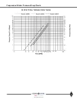
Страница 29: ...27 www climacoolcorp com Evaporator Water Pressure Drop Charts...
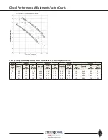
Страница 30: ...28 www climacoolcorp com Glycol Performance Adjustments Factor Charts...
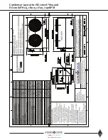
Страница 41: ...39 www climacoolcorp com Condenser Layout for RC1 007A H24 and RC1 008A H24 1 Row 2 Fan 1140RPM...
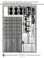
Страница 42: ...40 www climacoolcorp com Condenser Layout for RC2 019A 026A and 31A H48 and RC2 038A H44 2 Row 4 Fan 1140RPM...
Страница 43: ...41 www climacoolcorp com Condenser Layout for RC2 018A X48 RC2 026A X40 and RC2 032A X44 2 Row 4 Fan 830 RPM...
Страница 47: ...45 www climacoolcorp com 45 www climacoolcorp com Condenser Layout for RC2 048A Q82 2 Row 8 Fan 540RPM...
Страница 78: ...76 www climacoolcorp com Wiring Diagram...
Страница 79: ...77 www climacoolcorp com Wiring Diagram...
Страница 80: ...78 www climacoolcorp com Wiring Diagram CoolLogic Control Panel...
Страница 81: ...79 www climacoolcorp com Wiring Diagram CoolLogic Control Panel...


