53
www.climacoolcorp.com
1
Doc: Remote condsr war agreement
SD #0025 Rev. 04.25.22
Remote Condenser Warranty Agreement
• Fax: 405.815.3000
By signing below, the Installing Contractor warrants the accuracy of the informati on contained in this document. Further, by signing below, the Installati on
Contractor warrants that the installati on work scope will include but shall not be limited to ALL of the items presented herein. Failure to provide accurate
informati on and/or the failure to follow the above minimum installati on instructi ons may result in an interrupti on in and/or cause the Warranty provided
on the unit to be void. A� er completi ng this document, please e-mail:
technical [email protected]
or Fax 405.815.3000.
Installing Contractor
Date
Project Name:
Project Address:
Installing Contractor Name (Print):
Date:
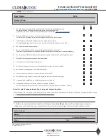
In the le� -hand margin, indicate you have verifi ed the accuracy of each line item by ini� aling each numbered item below.
1. Minimum Order Temperature for Condenser Design
The minimum winter outdoor temperature for design is
(check one)
: +45°F 20°F -20°F
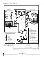
For +45F: 2-Stage Condenser fan cycling by refrigerant pressure is standard opti on for +45F minimum outdoor.
(See Refrigerati on Circuit Diagram).
For +20F: Pressure fan cycling on all stages except variable speed header fan(s) (See Refrigerati on Circuit Diagram).
For -20F: Flooded head pressure control must be factory approved. All condenser fans except the header end fan
will cycle on individual pressure fan cycling controls. Field installed fl ooded head pressure controls are required
(See Refrigerati on Circuit Diagram).
2. Compressor Hot Gas Bypass
Each module can be equipped with Hot Gas Bypass on both circuits. If required, is this opti on in place?: Yes
No
3. A/C Condenser Loca� on rela� ve to Chiller Module
A/C Condenser is located at a HIGHER elevati on relati ve to chiller Module Yes
No
4. Refrigerant Piping Geometry to Remote A/C Condenser; Ver� cal Distance
A/C Condenser is located
Less than 10 feet Higher Eleva� on
relati ve to chiller module
� .
A/C Condenser is located
Less than 30 feet Higher Eleva� on
relati ve to chiller module
� .
5. Refrigerant Piping Geometry to Remote A/C Condenser; Horizontal Distance
A/C Condenser is located at an aggregate total distance equal to the sum of the verti cal distance from Item 4 above plus
the total horizontal distance, which
SHALL NOT EXCEED 100 FEET
. Enter the distance:
� .
6. Refrigerant Piping Geometry to Remote A/C Condenser; Oil Return “P” Traps
The installing contractor MUST agree to the installati on of the following: If the A/C Condenser is located
Greater than
10 feet Higher Eleva� on
relati ve to the chiller module, install ALL inverted “P” traps as shown on Remote Condenser
Installati on Guidelines drawing.
7. Refrigerant Piping Geometry to Remote A/C Condenser; Oil Return “P” Traps with Hot Gas Bypass
If the module is equipped with hot gas bypass the installing contractor MUST agree to the installati on of the following: If the
A/C Condenser is located
Greater than 10 feet Higher Eleva� on
relati ve to the chiller module, install ALL inverted “P” traps
with double verti cal riser lines as shown on Remote Condenser Installati on Guidelines drawing.
8. Refrigerant Piping Geometry to Remote A/C Condenser; Sloped for Oil Return
The installing contractor MUST agree to the installati on of the following: The discharge line to the Condenser AND the
condenser liquid return line to the module must slope downward in the directi on of the refrigerant fl ow at 1/8” per foot.
9. Refrigerant Piping Geometry to Remote A/C Condenser; Isola� on and Check Valves
The installing contractor MUST agree to the installati on of the following: All necessary isolati on and check valves as shown
on the Remote Condenser Installati on Guidelines drawing and the Refrigerati on Circuit Diagram.
10. Refrigerant Piping Geometry to Remote A/C Condenser; NO change in ^/˅ Direc� on
Starti ng at the module, the discharge line to condenser and the condenser liquid return line from condenser DO NOT have
any changes in the elevati on directi on throughout the piping runs, e.g. UP 20 feet, then DOWN 10 feet to the condenser
connecti ons. In other words, all piping runs MUST follow a Consistent Upward Path from the module to the condenser;
with the only excepti on being ⅛” per foot sloped piping, as outlined in Item 7 above.
Содержание CLIMACOOL UCR 30
Страница 19: ...17 www climacoolcorp com Voltage Phase Monitor Wiring Diagram...
Страница 29: ...27 www climacoolcorp com Evaporator Water Pressure Drop Charts...
Страница 30: ...28 www climacoolcorp com Glycol Performance Adjustments Factor Charts...
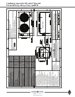
Страница 41: ...39 www climacoolcorp com Condenser Layout for RC1 007A H24 and RC1 008A H24 1 Row 2 Fan 1140RPM...
Страница 42: ...40 www climacoolcorp com Condenser Layout for RC2 019A 026A and 31A H48 and RC2 038A H44 2 Row 4 Fan 1140RPM...
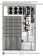
Страница 43: ...41 www climacoolcorp com Condenser Layout for RC2 018A X48 RC2 026A X40 and RC2 032A X44 2 Row 4 Fan 830 RPM...
Страница 47: ...45 www climacoolcorp com 45 www climacoolcorp com Condenser Layout for RC2 048A Q82 2 Row 8 Fan 540RPM...
Страница 78: ...76 www climacoolcorp com Wiring Diagram...
Страница 79: ...77 www climacoolcorp com Wiring Diagram...
Страница 80: ...78 www climacoolcorp com Wiring Diagram CoolLogic Control Panel...
Страница 81: ...79 www climacoolcorp com Wiring Diagram CoolLogic Control Panel...

