71
www.climacoolcorp.com
Pre Installation Checklist:
1 .
Ensure working conditions (pressure/temperature)
are within the specified capacity of the product being
installed. Please refer to the certified drawings to assist
in determining these values .
2 .
Inspect all sealing surfaces to ensure gasket surfaces
are free of defects (no nicks or cuts) . The pipeline
should also be checked for proper alignment . WYE
strainers should never be utilized to realign an existing
piping system .
3 .
Ensure that the pipeline’s mating flanges are the same
type as the WYE strainer being installed . Raised face
flange ends cannot be mated to flat face flange ends.
4 .
Ensure strainer end-to-end length and installation
gap are within 1/4 in gap for gasket, and have sufficient
clearance for easy opening of cover and screen removal .
5 .
If the WYE strainer is to be located on the discharge side
of a pump, then a safety release valve must be installed
between the WYE strainer and the pump .
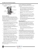
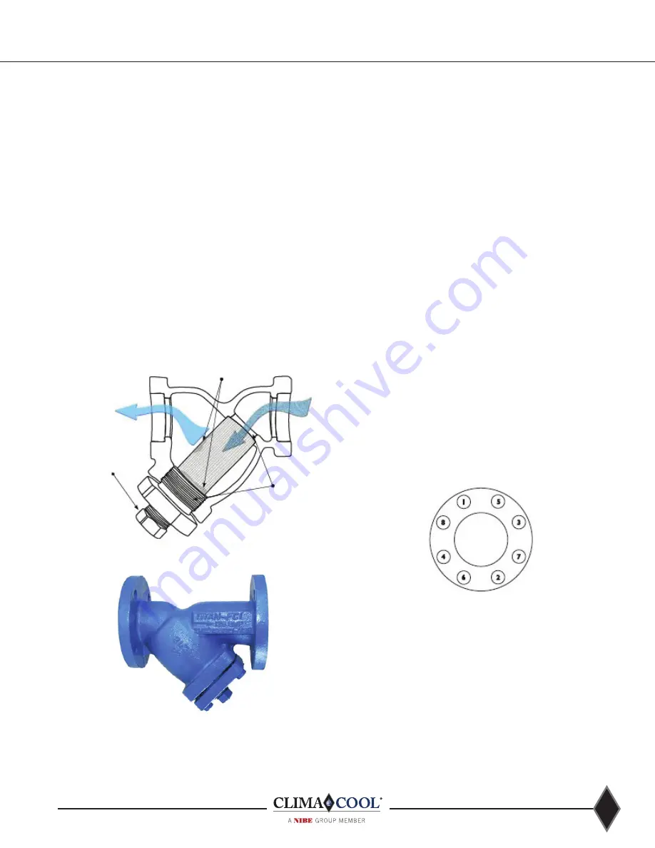
Figure 33: WYE Strainer Straining Illustration
High Particle Retention
& Accumulation Areas
Flitered
Flow
Unflitered
Flow
Machined Seats and Caps
for Fine Filtration
Manual or Automated
Valve Mounted to Blow Off
Enables Self Cleaning
Figure 34: WYE Strainer - Flanged Ends
WYE Strainers
Installation Procedure:
1 .
Also, for maximum efficiency, install a differential
pressure gauge at inlet and outlet connections or at the
strainer gauge tap (if provided) .
2 .
WYE strainers must be positioned in the pipeline ahead
of the equipment requiring protection .
3 .
To provide for easier maintenance, the WYE strainer
should be located where the drain plug can be removed .
Additionally, ensure the drain or blow-off is located at
the lowest position when installed . If installed in the
vertical position, the WYE side of the strainer must be
pointing downward .
4 .
Ensure there is ample space at the WYE side of the
strainer for screen removal .
5 .
Before placing the WYE strainer into place, support the
existing pipeline with pipe supports near the inlet and
outlet connections .
6 .
Place the WYE strainer into the pipeline ensuring
that the flow arrow on the body of the WYE strainer
is pointing in the direction of the pipeline flow. For
large or heavy strainers, appropriate material handling
equipment must be used .
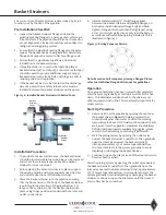
7 .
Install a standard ANSI (1/8” thick) flange gasket
between the WYE strainer and pipeline flanges, on
both sides. Install lubricated flange bolts and hand
tighten . Flange bolts should then be tightened, using
a star or crisscross pattern to evenly load the bolts, in
accordance with established piping standards . This is
illustrated in figure 35.
Figure 35: Bolting Sequence Pattern
Note: Excessive bolt torque may damage flanges. Please
refer to established flange bolt torques for guidelines.
Operation
Once proper installation has been successfully completed,
start the system gradually, at start up as well as after shut
down . This eliminates sudden shock to the strainer and
other equipment in the line . This is extremely important for
steam service .
Содержание CLIMACOOL UCR 30
Страница 19: ...17 www climacoolcorp com Voltage Phase Monitor Wiring Diagram...
Страница 29: ...27 www climacoolcorp com Evaporator Water Pressure Drop Charts...
Страница 30: ...28 www climacoolcorp com Glycol Performance Adjustments Factor Charts...
Страница 41: ...39 www climacoolcorp com Condenser Layout for RC1 007A H24 and RC1 008A H24 1 Row 2 Fan 1140RPM...
Страница 42: ...40 www climacoolcorp com Condenser Layout for RC2 019A 026A and 31A H48 and RC2 038A H44 2 Row 4 Fan 1140RPM...
Страница 43: ...41 www climacoolcorp com Condenser Layout for RC2 018A X48 RC2 026A X40 and RC2 032A X44 2 Row 4 Fan 830 RPM...
Страница 47: ...45 www climacoolcorp com 45 www climacoolcorp com Condenser Layout for RC2 048A Q82 2 Row 8 Fan 540RPM...
Страница 78: ...76 www climacoolcorp com Wiring Diagram...
Страница 79: ...77 www climacoolcorp com Wiring Diagram...
Страница 80: ...78 www climacoolcorp com Wiring Diagram CoolLogic Control Panel...
Страница 81: ...79 www climacoolcorp com Wiring Diagram CoolLogic Control Panel...


