13
www.climacoolcorp.com
Unit Placement
ClimaCool modular chillers must be installed in a
conditioned and dehumidified space. The minimum
foundation requirement for the ClimaCool chiller is a level
surface capable of bearing the combined operating weight
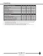
of the modules (see Physical Data - page 5) .
Service Access
The recommended service clearances are 36” for front
service access, 18” height clearance for service and 30” for
rear service access as identified in the Recommended Service
Clearances on page 11 . Local building or electrical codes may
require additional clearance – consult applicable codes .
Draining
When performing standard maintenance procedures such
as flushing a heat exchanger, it will be necessary to close
off a section of a module. ClimaCool modular chillers offer
optional water isolation valves for this purpose . Access
to a floor drain is helpful when performing standard
maintenance procedures .
Warning: Water valves must be
reopened after flushing is complete.
Assembling Modules
ClimaCool recommends locking down the chiller to a
concrete base, or to three (3) 4” base mounting rails, using
the six (6) bolt holes provided in each base pan . Although
the compressors are installed on anti-vibration mountings,
further isolation of the chiller from the structure is
recommended by installing vibration — eliminating springs
or pads under the base rails on which the chiller will rest
(see page 10 – Mounting Rail and Vibration Isolation) . One
end of the modules should be chosen as the reference
module and carefully located .
Field installed mounting accessories are provided for
adjoining each module .
• Header grooved coupling kits containing two (2) grooved
couplings with gaskets .
• Mounting hardware kit containing necessary bolts,
spacers, nuts and washers .
• Header bank end cap kit containing two (2) grooved
couplings with gaskets and two (2) end caps .
Unit Installation
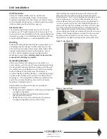
Field installing the mounting hardware kit will assist with
alignment of the modules in a bank and eliminate offset
inconsistencies. The 1/2” mounting holes are provided on sides
of the unit base pan. The first module should be set, then
set the adjacent unit on mounting surface roughly aligned
1 ½ inches away from the first unit. While holding spacer in
place, work through first modules front base cutout to place
a washer and insert bolt through front mounting hole and
spacer . Repeat the process for the rear mounting hole . Line
up mounting hole of adjacent module with bolt from previous
module . Work through adjacent modules front base cutout
by placing a washer, split lock washer and nut . Using the
appropriate tools, tighten hardware assembly until seated .
Figure 8 - Hardware Kit
Figure 9 - Spacer Holes
END TO END SPACER HOLES
Содержание CLIMACOOL UCR 30
Страница 19: ...17 www climacoolcorp com Voltage Phase Monitor Wiring Diagram...
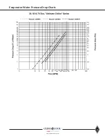
Страница 29: ...27 www climacoolcorp com Evaporator Water Pressure Drop Charts...
Страница 30: ...28 www climacoolcorp com Glycol Performance Adjustments Factor Charts...
Страница 41: ...39 www climacoolcorp com Condenser Layout for RC1 007A H24 and RC1 008A H24 1 Row 2 Fan 1140RPM...
Страница 42: ...40 www climacoolcorp com Condenser Layout for RC2 019A 026A and 31A H48 and RC2 038A H44 2 Row 4 Fan 1140RPM...
Страница 43: ...41 www climacoolcorp com Condenser Layout for RC2 018A X48 RC2 026A X40 and RC2 032A X44 2 Row 4 Fan 830 RPM...
Страница 47: ...45 www climacoolcorp com 45 www climacoolcorp com Condenser Layout for RC2 048A Q82 2 Row 8 Fan 540RPM...
Страница 78: ...76 www climacoolcorp com Wiring Diagram...
Страница 79: ...77 www climacoolcorp com Wiring Diagram...
Страница 80: ...78 www climacoolcorp com Wiring Diagram CoolLogic Control Panel...
Страница 81: ...79 www climacoolcorp com Wiring Diagram CoolLogic Control Panel...


