36
www.climacoolcorp.com
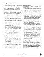
Head Pressure Control Valve Operation (LAC-10)
Charging of Systems with Sporlan Head Pressure
Control in Ambient ABOVE 70°F
(After normal evacuation procedures)
Before starting system:
1 .
Connect refrigerant cylinder to a charging or gauge
port on the receiver outlet valve .
2 .
Open the receiver valve approximately one-half way
(so receiver and liquid line are connected to charging
or gauge port) .
3 .
Charge liquid refrigerant into the high side of the system .
Weighing the charge is recommended with
the initial charge consisting of approximately 2 .5 pounds
per system ton .
4 .
Remove the refrigerant drum and connect it to the
suction side of the compressor .
5 .
Charge refrigerant vapor into the low side until the
pressure is above atmospheric pressure . Do not admit
liquid refrigerant into the low side .
6 .
Start the system .
7 .
Observe sight glass (at receiver outlet) to see if system
is properly charged for normal refrigeration cycle .
CAUTION: Bubbles in the sight glass can be caused by
flashing due to pressure drop from pipe or accessory
losses, etc.
8 .
If the sight glass shows bubbles, more refrigerant
should be added, while allowing sufficient time for the
refrigerant to stabilize and clear the sight glass .
9 .
The extra refrigerant charge for head pressure control
should be weighed in now by admitting liquid refrigerant
to the high side .
Charging of Systems with Sporlan Head Pressure
Control in Ambient BELOW 70°F
(After normal evacuation procedures)
Note:
When charging in ambient below 70°F the procedure
is very critical . Be sure to adhere to the following steps
without fail . Failure to do so will result in overcharging
the system .
1 .
Follow instructions 1 through 9 above .
2 .
If the LAC valve setting is correct for the system being
charged, it is quite likely that some refrigerant will be
backed up into the condenser and the sight glass will
indicate bubbles in the liquid line .
3 .
Add more refrigerant, while allowing sufficient time for
the refrigerant to stabilize and clear the sight glass .
4 .
At this point the system is correctly charged for this type
of head pressure control at the ambient temperature
that exists while the charging procedure is taking place .
5 .
If the system is designed to operate at ambient below
the ambient that exists during charging, additional
charge will have to be added now .
6 .
To calculate the additional charge required, follow the
examples outlined under the Refrigerant Charge section .
Remember that the “head pressure control charge” is
partially charged already . Refer to Tables 9 and 10 .
The difference in percentages between the minimum
design
ambient temperature and the ambient temperature at the
time the system is charged gives the percent of
extra
charge
still needed in the system . Example: if this system was
charged at an ambient of 50°F, there is approximately 40%
of the
extra
charge in the system . This holds true as long as
the compressor is not allowed to unload during charging .
Therefore, the additional charge required is 95 minus 40 or
55% of the total
extra
charge calculated previously . This is
.55 x 119 or 65 pounds .
Service Procedures
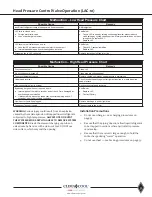
There are several possible causes for system malfunction
with “refrigerant side” head pressure control and these
may be difficult to isolate from each other. As with any
form of system trouble-shooting, it is necessary to know
the existing operating temperatures and pressures
before system problems can be determined . Once the
actual malfunction is established, it is easier to pinpoint
the cause and then take suitable corrective action . The
following chart lists the most common malfunctions, the
possible causes, and the remedies . Since the LAC valves are
hermetic, the valves cannot be disassembled for inspection
and/or replacement of parts . The valves must be replaced
if they become inoperative .
Содержание CLIMACOOL UCR 30
Страница 19: ...17 www climacoolcorp com Voltage Phase Monitor Wiring Diagram...
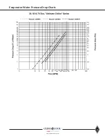
Страница 29: ...27 www climacoolcorp com Evaporator Water Pressure Drop Charts...
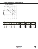
Страница 30: ...28 www climacoolcorp com Glycol Performance Adjustments Factor Charts...
Страница 41: ...39 www climacoolcorp com Condenser Layout for RC1 007A H24 and RC1 008A H24 1 Row 2 Fan 1140RPM...
Страница 42: ...40 www climacoolcorp com Condenser Layout for RC2 019A 026A and 31A H48 and RC2 038A H44 2 Row 4 Fan 1140RPM...
Страница 43: ...41 www climacoolcorp com Condenser Layout for RC2 018A X48 RC2 026A X40 and RC2 032A X44 2 Row 4 Fan 830 RPM...
Страница 47: ...45 www climacoolcorp com 45 www climacoolcorp com Condenser Layout for RC2 048A Q82 2 Row 8 Fan 540RPM...
Страница 78: ...76 www climacoolcorp com Wiring Diagram...
Страница 79: ...77 www climacoolcorp com Wiring Diagram...
Страница 80: ...78 www climacoolcorp com Wiring Diagram CoolLogic Control Panel...
Страница 81: ...79 www climacoolcorp com Wiring Diagram CoolLogic Control Panel...

