background image

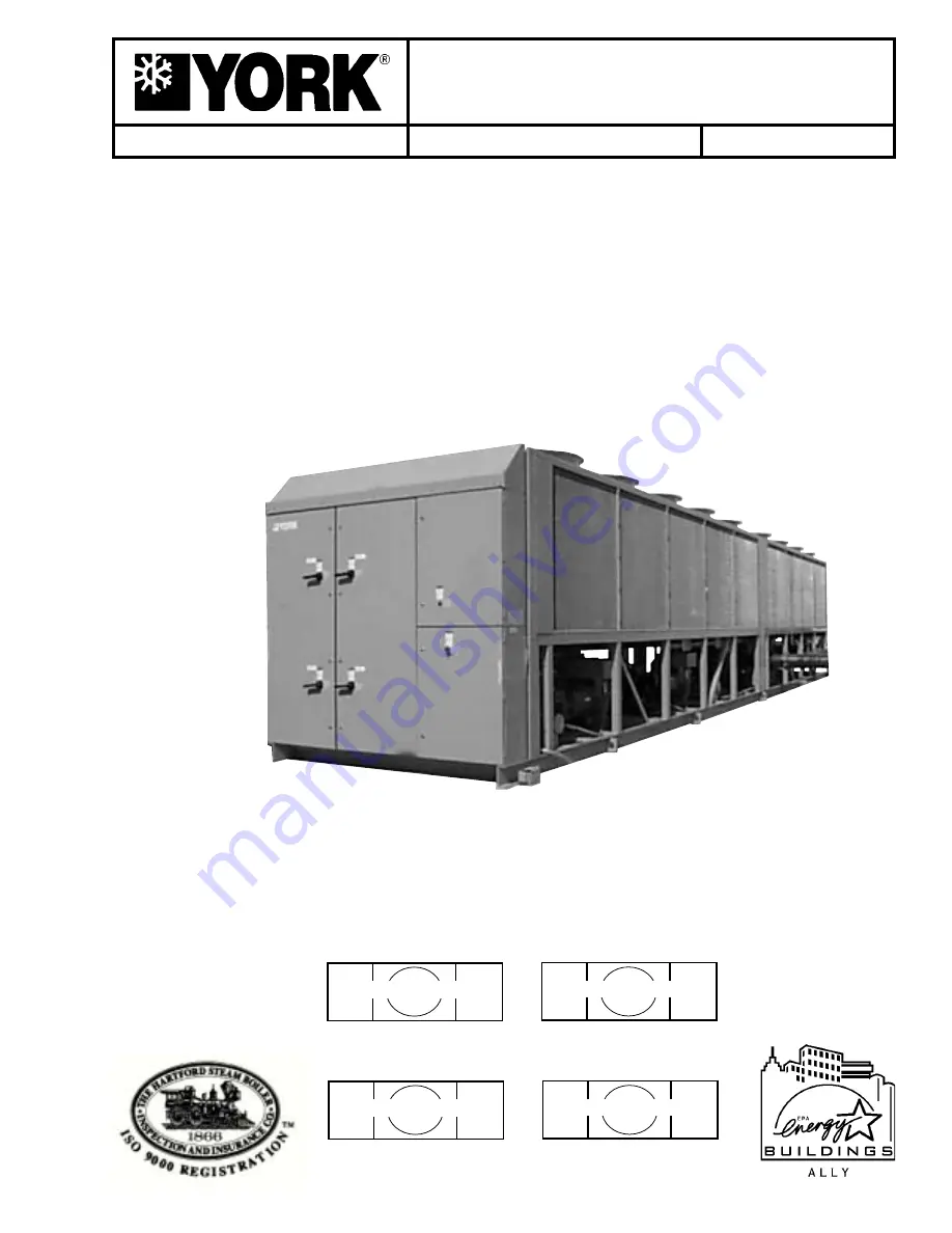
INSTALLATION, OPERATION & MAIN TE NANCE

AIR-COOLED SCREW LIQUID CHILLERS

New Release

Form 201.19-NM6 (804)

YCAS AIR-COOLED LIQUID CHILLERS

YCAS0693EC THROUGH YCAS0953EC (3 COMPRESSOR)
YCAS1063EC THROUGH YCAS1263EC (4 COMPRESSOR)

 STYLE G  R-22

50 Hz

I/O BOARD #2 EPROM

031-02018-001

MICROPROCESSOR BOARD

031-01798-002

(YCAS 3 SYSTEM EPROMs)

(YCAS 4 SYSTEM EPROMs)

I/O BOARD #2 EPROM

031-02018-001

MICROPROCESSOR BOARD

031-01798-002

035-20884-000

00258VIP

Содержание YCAS

Страница 1: ...QUID CHILLERS YCAS0693EC THROUGH YCAS0953EC 3 COMPRESSOR YCAS1063EC THROUGH YCAS1263EC 4 COMPRESSOR STYLE G R 22 50 Hz I O BOARD 2 EPROM 031 02018 001 MICROPROCESSOR BOARD 031 01798 002 YCAS 3 SYSTEM...

Страница 2: ...l owner that information if applicable can be obtained by contacting the nearest YORK Engineered Systems Service office It is the responsibility of operating service personnel to verify the applicabil...

Страница 3: ...aterials This individual shall also be familiar with and comply with all applicable governmental standards and regulations pertaining to the task in question SAFETY SYMBOLS The following symbols are u...

Страница 4: ...Automation System BAS Interface 21 Condenser Coil Protection 21 DX EVAPORATOR AND STARTER OPTIONS 22 UNIT ENCLOSURE OPTIONS 22 FAN OPTIONS 22 SOUND REDUCTION OPTIONS 22 VIBRATION ISOLATION 22 UNIT NOM...

Страница 5: ...MULTIPLE POINT POWER SUPPLY CONNECTION 50 ELECTRICAL DATA 52 ELECTRICAL NOTES 54 ELEMENTARY WIRING DIAGRAM YCAS0693 YCAS0953 3 COMPRESSOR 56 CONNECTION DIAGRAM ELEC BOX YCAS0693 YCAS0953 62 CONNECTIO...

Страница 6: ...56 3 2 Chilled Liquid Temps Key 156 3 3 System Data Keys 157 3 4 Ambient Temp Key 157 3 5 Motor Current Key 158 3 6 Operating Hrs Start Counter Key 158 3 7 Options Key Dip Switch Settings 158 3 8 Func...

Страница 7: ...ES TABLE 183 TABLE 4 PROGRAMMABLE VALUES TABLE MINIMUM MAXIMUM 187 TABLE 5 CONDENSER FAN CONTROL AND FAN CONTACTOR DATA FOR DXST UNITS 189 TABLE 6 CONDENSER FAN CONTROL AND FAN CONTACTOR DATA FOR DXST...

Страница 8: ...MENTARY WIRING DIAGRAM 4 COMPRESSOR 72 FIG 35 ELEMENTARY WIRING DIAGRAM ACROSS THE LINE START 73 FIG 36 ELEMENTARY WIRING DIAGRAM WYE DELTA 74 FIG 37 CONTROL POWER TRANSFORMER KIT 75 FIG 38 ELEMENTARY...

Страница 9: ...ce that the failure has occurred within the warranty period and that the unit has been operated within the designed parameters specified All warranty claims must specify the unit model serial number o...

Страница 10: ...EQUIPMENT Suitability for Application The unit is intended for cooling water or glycol solutions and is not suitable for purposes other than those specified in these instructions Any use of the equip...

Страница 11: ...s recommended Refrigerants and Oils Refrigerants and oils used in the unit are generally non toxic non flammable and non corrosive and pose no special safety hazards Use of gloves and safety glasses a...

Страница 12: ...allic conduit General Description TheAir Cooled Screw Chiller utilizes many components which are the same or nearly the same as a standard reciprocating chiller of a similar size This includes modular...

Страница 13: ...refrigerant using an external oil separator The pressurized oil from the oil separator is then cooled in the condenser coils and piped back to the compressor for lubrication The compressor design wor...

Страница 14: ...alve is controlled by the microprocessor The valve will remain off for the first 3 minutes of compressor operation After 3 minutes of operation the economizer solenoid valve will open if the slide val...

Страница 15: ...ection contains ON OFF switch microcomputer keypad and display microprocessor board I O expansion board relay boards and power supply board The options sections contain A control circuit transformer c...

Страница 16: ...o senses the low motor current and shuts the system down The micro will try two more starts before locking the system out The system locks out because the motor protector is a manual re set device Aft...

Страница 17: ...ompares the Operating Current to the measured half line current The Operating Current is given by 0 65 X factory overload current setting An unloaded compressor condition occurs when any measured half...

Страница 18: ...3 Sys 1 2 50 140 2 189 1 0 1 1 1 1 0 1 0773 Sys 3 50 183 2 124 0 1 1 1 1 1 0 0 0783 Sys 1 2 50 124 2 167 1 0 1 0 0 1 1 1 0783 Sys 3 50 168 2 113 0 1 1 1 0 0 0 1 0873 50 168 2 113 0 1 1 1 0 0 0 1 0953...

Страница 19: ...1 0 1 1 1 1 0 1 693 Sys 3 50 124 2 167 1 0 1 0 0 1 1 1 0773 Sys 1 2 50 140 2 189 1 0 1 1 1 1 0 1 0773 Sys 3 50 183 2 143 1 0 0 0 1 1 1 1 0783 Sys 1 2 50 124 2 167 1 0 1 0 0 1 1 1 0783 Sys 3 50 168 2...

Страница 20: ...elay is enabled by the microprocessor from Relay Output Board 1 Terminal 8 SYS 1 or Relay Output Board 2 Terminal 6 SYS 2 The 1TR SYS 1 or 2TR SYS 2 contacts open de energizing 1S SYS 1 or 2S SYS 2 1M...

Страница 21: ...he fins and other corrosive applications except strong alkalis oxidizers and wet bromine chlorine and fluorine in concentrations greater than 100 PPM The standard display language is English with 4 ot...

Страница 22: ...nclosure Heavy gauge welded wire mesh guards mounted on the exterior of the unit Factory or field mounted Louvered panels and wired guards Louvered pan els mounted over the exterior condenser coil fac...

Страница 23: ...eset Offset Special BAS Reset Offset Required English LCD Keypad Display std Spanish LCD Keypad Display French LCD Keypad Display German LCD Keypad Display Italian LCD Keypad Display Special LCD Keypa...

Страница 24: ...und Fans Low Sound Fans High Static Fans Special Sound Fans No Final Overspray Paint Required Final Overspray Paint Special Overspray Paint Required No Vibration Isolators 1 Vibration Isolators Seismi...

Страница 25: ...not be steam cleaned It is recommended that the unit is periodically in spected during storage INSPECTION Remove any transit packing and inspect the unit to en sure that all components have been deli...

Страница 26: ...26 YORK INTERNATIONAL FORM 201 19 NM6 804 88 2250mm UNIT RIGGING CORRECT WRONG LD03514 FIG 3 UNIT RIGGING CORRECT WRONG LD03515 FIG 4 LIFTING LUGS CORRECT WRONG Handling and Storage...

Страница 27: ...must be at least 4 3 4 120 mm wide at the contact points This will allow vibration isolators to be fitted if required Any ductwork or attenuators fitted to the unit must not have a total static press...

Страница 28: ...from the base rails DO NOT remove the four 3 8 bolts 3 mounting the corner brackets 2 to the frame rails 1 2 2 COMPRESSOR CHANNEL BASE BASE SUPPORT RAIL 3 3 LD09131 FIG 5 COMPRESSOR MOUNTING Where ac...

Страница 29: ...at any time Refer to the Technical Data Section for details The liquid must enter the evaporator at the inlet connection The inlet con nection for the evaporator is at the control panel end of the un...

Страница 30: ...insulation is recommended supplied independently and controlled by an ambient temperature thermostat set to switch on at 37 F 21 C above the freezing temperature of the liquid The liquid circulation...

Страница 31: ...at the outlet of relief valves vent pipe remain clear of obstructions at all times DUCTWORK CONNECTION General Requirements The following ductwork recommendations are intended to ensure satisfactory o...

Страница 32: ...install overcurrent protection devices between the supply conductors and the power supply terminals on the unit To ensure that no eddy currents are set up in the power panel the cables forming each 3...

Страница 33: ...erminals 29 and 30 Figs 13 and 14 pages 38 and 39 close to indicate that a system is running Alarm Contacts Each system has a voltage free change over contact which will operate to signal an alarm con...

Страница 34: ...34 YORK INTERNATIONAL FORM 201 19 NM6 804 POWER PANEL LAYOUTS TYPICAL FIG 9 POWER PANEL SECTION 00263VIP Installation WYE DELTA TYPICAL...

Страница 35: ...35 YORK INTERNATIONAL FORM 201 19 NM6 804 4 FIG 10 OPTION PANEL SECTION OPTION PANEL LAYOUT TYPICAL 00246VIP...

Страница 36: ...SECTION FIG 11 LOGIC SECTION LAYOUT LOGIC SECTION LAYOUT 00247VIP ITEM 1 2 3 4 5 6 7 8 DESCRIPTION Microprocessor Board I O Board 2 I O Expansion Board 1 Power Supply Board Relay Output Board 1 Relay...

Страница 37: ...37 YORK INTERNATIONAL FORM 201 19 NM6 804 4 FIG 12 LOGIC SECTION LAYOUT WITH CONTROL PANEL LOGIC SECTION LAYOUT WITH CONTROL PANEL 00248VIP...

Страница 38: ...rrent PWM Flow Switch System No 1 Run System No 2 Run 13 13 13 13 13 14 15 16 17 18 19 23 24 25 26 27 28 29 30 System No 1 Alarm Contacts Chilled Liquid Circulating Pump Start System No 2 Alarm Contac...

Страница 39: ...4 FIG 14 CUSTOMER CONNECTIONS CUSTOMER CONNECTIONS CIRCUIT BREAKERS CB1 CB5 00247VIP MICROPROCESSOR CIRCUIT BOARD RELAY BOARDS I O EXPANSION BOARD 1 TRANSFORMERS CUSTOMER CONNECTIONS Flow Switch Alarm...

Страница 40: ...e options panel It is important to check that the correct primary tapping has been used With the supply voltage to the unit turned off remove the lid to the transformer box SECTION 5 COMMISSIONING PRE...

Страница 41: ...fitted in the customer s pipework on the evaporator outlet and wired into the control panel correctly using shielded cable There should be a straight run of at least 5 pipe diameters on either side of...

Страница 42: ...g a full charge of refrigerant is in the system the bubbles will disappear and be replaced by a solid column of liquid Fan Rotation As discharge pressure rises the condenser fans operate in stages to...

Страница 43: ...43 YORK INTERNATIONAL FORM 201 19 NM6 804 5 This page intentionally left blank...

Страница 44: ...ons are fully automatic After an initial period at minimum capacity on the lead compressor the control system will adjust the unit load depending on the chilled liquid temperature and rate of temperat...

Страница 45: ...45 YORK INTERNATIONAL FORM 201 19 NM6 804 6 This page intentionally left blank...

Страница 46: ...sive flow above the max GPM will damage the evaporator GLYCOL CORRECTION FACTORS ETHYLENE GLYCOL PROPYLENE GLYCOL A A B B C C 1 45 1 40 1 35 1 30 1 25 1 20 1 15 1 10 1 05 1 8 1 7 1 6 1 5 1 4 1 3 1 2 1...

Страница 47: ...lication guidelines 3 The evaporator is protected against freeze up to 28 8 C with an electrical heater as standard MODEL NUMBER YCAS LEAVING WATER TEMPERATURE C COOLER FLOW L S 3 AIR ON CONDENSER C M...

Страница 48: ...35 67 47 57 47 57 47 57 47 57 Number of Rows 3 3 3 3 3 3 3 3 3 Fins per Meter 512 512 512 512 512 512 512 512 512 Condenser Fans Number Ckt 1 Ckt 2 3 3 3 3 4 4 4 4 4 4 5 5 4 4 4 4 4 4 Number Ckt 3 Ck...

Страница 49: ...ANS 18 46 CONDENSER C LOW NOISE FANS 18 46 FAN STANDARD FANS 20 AVAILABLE STATIC HIGH PRESS FANS OPTION 1 85 PRESSURE Pa HIGH PRESS FANS OPTION 2 150 LOW NOISE FANS 10 200 230 ELECTRICAL THREE PHASE 6...

Страница 50: ...0873 380 457 600 500 500 2 1 0 300 2 250 500 168 283 907 168 283 907 8 4 4 17 1 0953 380 494 600 500 600 2 1 0 300 2 250 500 183 283 907 183 283 907 8 4 4 17 1 1063 380 413 600 450 500 2 1 0 300 2 250...

Страница 51: ...300 2 4 0 4 300 140 283 907 3 4 4 17 1 0773 380 189 200 200 300 2 4 0 4 300 140 283 907 3 4 4 17 1 0783 380 173 175 175 250 2 4 0 4 300 124 283 907 4 4 4 17 1 0873 380 228 250 250 350 1 0 300 6 350 1...

Страница 52: ...Provided Power Supply Factory Provided Lugs Wire Range7 Model YCAS Volts MRA1 Min NF Over Current Protection13 Terminal Block NF Disc Switch MCA Disc SW2 Min 3 5 Max 4 6 Lugs Wire Range Lugs Wire Rang...

Страница 53: ...283 907 8 4 4 17 1 161 283 907 140 283 907 8 4 4 17 1 183 283 907 140 283 907 7 4 4 17 1 168 283 907 168 283 907 8 4 4 17 1 183 283 907 183 283 907 8 4 4 17 1 ELECTRICAL SYSTEM 2 FIELD SUPPLIED WIRIN...

Страница 54: ...re available per phase Actual wire size and number of wires per phase must be determined based on ampacity and job requirements using N E C wire sizing information The above recommendations are based...

Страница 55: ...0 150 150 150 113 150 105 105 105 105 80 105 MAX AMPS 492 428 259 214 193 171 492 428 259 214 193 171 338 294 178 147 135 118 CONTROL POWER SUPPLY UNITS WITHOUT STANDARD CONTROL CIRCUIT TRANSFORMER NO...

Страница 56: ...YORK INTERNATIONAL FORM 201 19 NM6 804 Technical Data ELEMENTARY WIRING DIAGRAM YCAS0693 YCAS0953 3 COMPRESSOR FIG 20 ELEMENTARY WIRING DIAGRAM DXST DIRECT DRIVE 3 COMPRESSOR LD09350 035 15937 103 Rev...

Страница 57: ...INTERNATIONAL FORM 201 19 NM6 804 FIG 21 ELEMENTARY WIRING DIAGRAM ACROSS THE LINE START 3 COMPRESSOR 7 ELEMENTARY WIRING DIAGRAM YCAS0693 YCAS0953 3 COMPRESSOR ACROSS THE LINE START LD09352 035 15937...

Страница 58: ...TERNATIONAL FORM 201 19 NM6 804 Technical Data FIG 22 ELEMENTARY WIRING DIAGRAM WYE DELTA START 3 COMPRESSOR ELEMENTARY WIRING DIAGRAM YCAS0693 YCAS0953 3 COMPRESSOR WYE DELTA START 035 15937 103 Rev...

Страница 59: ...t installed a jumper must be connected between terminals 5 and 1 Device must have a minimum contact rating of 100A at 115 volts A C 5 Alarm contacts are for annunciating alarm unit malfunc tion Contac...

Страница 60: ...60 YORK INTERNATIONAL FORM 201 19 NM6 804 Technical Data FIG 24 ELEMENTARY WIRING DIAGRAM DXST DIRECT DRIVE CONTROL CIRCUIT LD09354 ELEMENTARY WIRING DIAGRAM YCAS0693 YCAS0953 3 COMPRESSOR...

Страница 61: ...ed in series with the flow switch for start stop into the Alarm circuitry or pilot relays for pump starters wired through motor contactor auxiliary contacts must be suppressed with YORK P N 031 00808...

Страница 62: ...62 YORK INTERNATIONAL FORM 201 19 NM6 804 Technical Data FIG 25 CONNECTION DIAGRAM 3 COMPRESSOR LD09362a CONNECTION DIAGRAM ELEC BOX YCAS0693 YCAS0953...

Страница 63: ...63 YORK INTERNATIONAL FORM 201 19 NM6 804 7 FIG 26 CONNECTION DIAGRAM 3 COMPRESSOR POWER PANEL LD09358 Power Panel 035 19205 104 Rev A...

Страница 64: ...64 YORK INTERNATIONAL FORM 201 19 NM6 804 Technical Data FIG 27 CONNECTION DIAGRAM 3 COMPRESSOR POWER PANEL LD09356 CONNECTION WIRING DIAGRAM Power Panel 035 19205 104 Rev A...

Страница 65: ...65 YORK INTERNATIONAL FORM 201 19 NM6 804 7 LD09359 Electronic Panel 035 19205 104 Rev A...

Страница 66: ...66 YORK INTERNATIONAL FORM 201 19 NM6 804 Technical Data LD09360 FIG 28 CONNECTION DIAGRAM 3 COMPRESSOR POWER PANEL Power Panel 035 19205 105 Rev A...

Страница 67: ...67 YORK INTERNATIONAL FORM 201 19 NM6 804 7 FIG 29 CONNECTION DIAGRAM 3 COMPRESSOR ELECTRONIC PANEL LD09361 CONNECTION WIRING DIAGRAM Electronic Panel 035 19205 105 Rev A...

Страница 68: ...IONAL FORM 201 19 NM6 804 Technical Data LD09363 2ACE Motor Protector 035 15937 102 Rev D ELEMENTARY DIAGRAM DXST DIRECT DRIVE CONTROL CIRCUIT FIG 30 ELEMENTARY DIAGRAM 3 COMPRESSOR DXST DIRECT DRIVE...

Страница 69: ...69 YORK INTERNATIONAL FORM 201 19 NM6 804 7 FIG 31 ELEMENTARY DIAGRAM DXST DIRECT DRIVE 3 COMPRESSOR LD09364 ELEMENTARY WIRING DIAGRAM 035 15937 102 Rev D...

Страница 70: ...70 YORK INTERNATIONAL FORM 201 19 NM6 804 Technical Data LD09365 CONNECTION DIAGRAM SYSTEM WIRING FIG 32 CONNECTION DIAGRAM SYSTEM WIRING 3 COMPRESSOR 035 19205 106 Rev...

Страница 71: ...71 YORK INTERNATIONAL FORM 201 19 NM6 804 7 FIG 33 CONNECTION DIAGRAM STSTEM WIRING 3 COMPRESSOR LD09366 CONNECTION DIAGRAM SYSTEM WIRING 035 19205 106 Rev...

Страница 72: ...72 YORK INTERNATIONAL FORM 201 19 NM6 804 Technical Data LD09367 FIG 34 ELEMENTARY WIRING DIAGRAM 4 COMPRESSOR ELEMENTARY WIRING DIAGRAM YCAS1063 YCAS1263 4 COMPRESSOR PAGE 76...

Страница 73: ...73 YORK INTERNATIONAL FORM 201 19 NM6 804 7 ELEMENTARY WIRING DIAGRAM YCAS1063 YCAS1263 4 COMPRESSOR LD09369 FIG 35 ELEMENTARY WIRING DIAGRAM ACROSS THE LINE START 035 16253 103 Rev A...

Страница 74: ...74 YORK INTERNATIONAL FORM 201 19 NM6 804 LD09370 FIG 36 ELEMENTARY WIRING DIAGRAM WYE DELTA ELEMENTARY WIRING DIAGRAM YCAS1063 YCAS1263 4 COMPRESSOR 035 16253 10 Rev A...

Страница 75: ...and 1 If a stop device is not installed a jumper must be connected between terminals 5 and 1 Device must have a minimum contact rating of 100A at 115 volts A C 5 Alarm contacts are for annunciating al...

Страница 76: ...76 YORK INTERNATIONAL FORM 201 19 NM6 804 LD09371 FIG 38 ELEMENTARY WIRING DIAGRAM ELEMENTARY WIRING DIAGRAM YCAS1063 YCAS1263 4 COMPRESSOR...

Страница 77: ...d in series with the flow switch for start stop into the Alarm circuitry or pilot relays for pump starters wired through motor contactor auxiliary contacts must be suppressed with YORK P N 031 00808 0...

Страница 78: ...78 YORK INTERNATIONAL FORM 201 19 NM6 804 YCAS 0358 0418 LD09375 FIG 39 CONNECTION DIAGRAM 4 COMPRESSOR YCAS1063 1263...

Страница 79: ...79 YORK INTERNATIONAL FORM 201 19 NM6 804 LD09376 FIG 40 CONNECTION DIAGRAM 4 COMPRESSOR Power Panel...

Страница 80: ...80 YORK INTERNATIONAL FORM 201 19 NM6 804 LD09377 FIG 41 ELEMENTARY WIRING DIAGRAM CONNECTION WIRING DIAGRAM Power Panel...

Страница 81: ...81 YORK INTERNATIONAL FORM 201 19 NM6 804 LD09378 CONNECTION WIRING DIAGRAM Electronic Panel...

Страница 82: ...82 YORK INTERNATIONAL FORM 201 19 NM6 804 LD09379 FIG 42 CONNECTION DIAGRAM 4 COMPRESSOR YCAS 0358 0418 YCAS1063 1263...

Страница 83: ...83 YORK INTERNATIONAL FORM 201 19 NM6 804 FIG 43 CONNECTION DIAGRAM 4 COMPRESSOR LD09380 Power Panel...

Страница 84: ...84 YORK INTERNATIONAL FORM 201 19 NM6 804 LD09381 FIG 44 CONNECTION DIAGRAM 4 COMPRESSOR CONNECTION WIRING DIAGRAM Power Panel...

Страница 85: ...85 YORK INTERNATIONAL FORM 201 19 NM6 804 LD09382 CONNECTION WIRING DIAGRAM Electronic Panel 035 19206 105 Rev A...

Страница 86: ...86 YORK INTERNATIONAL FORM 201 19 NM6 804 LD09373 ELEMENTARY DIAGRAM DXST DIRECT DRIVE CONTROL CIRCUIT FIG 45 ELEMENTARY DIAGRAM DXST DIRECT DRIVE CONTROL CIRCUIT 2ACE Motor Protector 035 16253 Rev B...

Страница 87: ...87 YORK INTERNATIONAL FORM 201 19 NM6 804 LD09374 FIG 46 ELEMENTARY DIAGRAM DXST DIRECT DRIVE CONTROL CIRCUIT 035 16253 102 Rev B ELEMENTARY DIAGRAM DXST DIRECT DRIVE CONTROL CIRCUIT...

Страница 88: ...ORM 201 19 NM6 804 LD09383 FIG 47 CONNECTION DIAGRAM SYSTEM WIRING CONNECTION DIAGRAM SYSTEM WIRING STANDARD AND REMOTE EVAP UNITS 035 19206 106 Rev CONNECTION DIAGRAM SYSTEM WIRING YCAS 1063 1263 STA...

Страница 89: ...89 YORK INTERNATIONAL FORM 201 19 NM6 804 LD09385 CONNECTION DIAGRAM SYSTEM WIRING STANDARD AND REMOTE EVAP UNITS FIG 48 CONNECTION DIAGRAM SYSTEM WIRING 035 19206 106 Rev...

Страница 90: ...90 YORK INTERNATIONAL FORM 201 19 NM6 804 LD09384 COMPRESSOR TERMINAL BOX SYSTEM 1 THROUGH 4 FIG 49 COMPRESSOR TERMINAL BOX SYSTEM 1 4 035 19206 106 Rev...

Страница 91: ...91 YORK INTERNATIONAL FORM 201 19 NM6 804 This page intentionally left blank...

Страница 92: ...imum clearances indicated below resulting in unpredictable air ow patterns and possible diminished performance YORK s unit controls will optimize operation without nuisance high pressure safety cutout...

Страница 93: ...201 19 NM6 804 DIMENSIONS YCAS0693 YCAS0773 SI A F E J D I C H B G LD03977 LD03978 CENTER OF GRAVITY Copper YCAS X Y Z 0693 3750 1008 907 0773 3751 1011 906 CENTER OF GRAVITY Alum YCAS X Y Z 0693 3732...

Страница 94: ...r winter operation or air recirculation ensures rated performance reliable operation and ease of maintenance Site restrictions may compromise minimum clearances indicated below resulting in unpredicta...

Страница 95: ...TER INLET 10 WATER OUTLET 2438 16 DIA MOUNTING HOLES TYP A B C D E F G H I J K L POWER ELEMENTS FOR SYS 1 3 POWER ELEMENTS FOR SYS 2 CONTROL PANEL 762 762 2235 ORIGIN 806 1453 1453 1453 1229 1400 32 3...

Страница 96: ...earances indicated below resulting in unpredictable air ow patterns and possible diminished performance YORK s unit controls will optimize operation without nuisance high pressure safety cutout howeve...

Страница 97: ...ERNATIONAL FORM 201 19 NM6 804 DIMENSIONS YCAS1063 SI 7 A G H B C D E F I O P J K L M N LD04017 LD04018 CENTER OF GRAVITY Alum YCAS X Y Z 1063 5738 1119 912 CENTER OF GRAVITY Copper YCAS X Y Z 1063 57...

Страница 98: ...ces indicated below resulting in unpredictable air ow patterns and possible diminished performance YORK s unit controls will optimize operation without nuisance high pressure safety cutout however the...

Страница 99: ...NTERNATIONAL FORM 201 19 NM6 804 DIMENSIONS YCAS1093 SI 7 A G M B C D E F H I J K L N LD03993 LD03994 CENTER OF GRAVITY Alum YCAS X Y Z 1093 5182 1120 883 CENTER OF GRAVITY Copper YCAS X Y Z 1093 5198...

Страница 100: ...for winter operation or air recirculation ensures rated performance reliable operation and ease of maintenance Site restrictions may compromise minimum clearances indicated below resulting in unpredic...

Страница 101: ...57 DIA RIGGING HOLES EACH SIDE A I B J C K D L E M F N G O H P 762 762 2235 ORIGIN 806 Y X 1453 1453 1453 923 1422 1422 1422 32 32 16 DIA MOUNTING HOLES TYP POWER ELEMENTS FOR SYS 1 3 POWER ELEMENTS...

Страница 102: ...804 TECHNICAL DATA CLEARANCES NOTES 1 No obstructions allowed above the unit 2 Only one adjacent wall may be higher than the unit 3 Adjacent units should be 10 feet 3 meters apart LD09409 FIG 55 CLEAR...

Страница 103: ...M N O P TOTAL 0693 850 774 897 642 649 850 864 1 019 958 1 066 8 569 0773 850 779 919 649 649 850 869 1 027 962 1 067 8 619 0783 856 790 945 659 582 383 856 884 1 055 970 977 383 9 341 0873 869 808 94...

Страница 104: ...ABLE BELOW 50 HZ A B C D E F G H I J K L M N O P YCAS0693 2 31 2 28 2 31 2 27 2 27 2 31 2 31 2 32 2 31 2 32 YCAS0773 2 31 2 28 2 31 2 27 2 27 2 31 2 31 2 32 2 31 2 32 YCAS0783 2 31 2 28 2 31 2 28 2 27...

Страница 105: ...1 530 1 553 2 53 2 521 1 553 2 530 1 530 YCAS0953 1 553 1 553 2 53 1 532 1 532 1 530 1 553 2 530 2 531 1 553 2 530 1 530 YCAS1063 1 552 1 553 1 553 2 520 2 520 2 53 2 520 1 553 1 552 1 553 1 553 2 52...

Страница 106: ...104 8 14 4 6 3 RD 3 R 4 6 1 4 4 5 8 1 5 8 2 3 4 3 1 2 5 9 16 3 8 OR 158 7 117 6 41 4 69 8 76 2 12 7 127 0 14 4 9 6 RD 4 DIMENSIONS ins mm HD dimension applies to double deflection Type RD mountings on...

Страница 107: ...1 055 1 138 9 332 0783 911 873 1 020 739 638 464 911 967 1 121 1 064 1 026 464 10 198 0873 923 891 1 022 906 1 137 466 923 875 681 957 1 028 466 10 275 0953 927 909 1 041 748 644 470 927 1 002 1 140...

Страница 108: ...EE TABLE BELOW 50 Hz A B C D E F G H I J K L M N O P YCAS0693 2 31 2 31 2 31 2 28 2 28 2 31 2 31 2 32 2 32 2 32 YCAS0773 2 31 2 31 2 31 2 28 2 28 2 31 2 31 2 32 2 32 2 32 YCAS0783 2 31 2 31 2 32 2 28...

Страница 109: ...1 1 530 1 553 2 53 2 521 1 553 2 530 1 530 YCAS0953 1 553 2 530 2 530 1 552 1 532 1 530 1 553 2 530 2 531 2 531 2 531 1 530 YCAS1063 1 553 2 53 2 530 2 520 2 520 2 530 2 520 1 553 1 553 2 53 2 530 2 5...

Страница 110: ...RD 3 R 4 6 1 4 4 5 8 1 5 8 2 3 4 3 1 2 5 9 16 3 8 OR 158 7 117 6 41 4 69 8 76 2 12 7 127 0 14 4 9 6 RD 4 DIMENSIONS ins mm HD dimension applies to double deflection Type RD mountings only Technical D...

Страница 111: ...862 982 725 728 904 951 1 084 1 055 1 138 9 332 0783 911 873 1 020 739 638 464 911 967 1 121 1 064 1 026 464 10 198 0873 923 891 1 022 906 1 137 466 923 875 681 957 1 028 466 10 275 0953 927 909 1 04...

Страница 112: ...SELECTIONS VMC TYPE CP SEE TABLE BELOW 50 Hz A B C D E F G H I J K L M N O P YCAS0693 2 31 2 31 2 31 2 28 2 28 2 31 2 31 2 32 2 32 2 32 YCAS0773 2 31 2 31 2 31 2 28 2 28 2 31 2 31 2 32 2 32 2 32 YCAS0...

Страница 113: ...2 53 2 530 1 553 2 531 1 530 1 553 2 53 2 521 1 553 2 530 1 530 YCAS0953 1 553 2 530 2 530 1 552 1 532 1 530 1 553 2 530 2 531 2 531 2 531 1 530 YCAS1063 1 553 2 53 2 530 2 520 2 520 2 530 2 520 1 55...

Страница 114: ...2 7 104 8 14 4 6 3 RD 3 R 4 6 1 4 4 5 8 1 5 8 2 3 4 3 1 2 5 9 16 3 8 OR 158 7 117 6 41 4 69 8 76 2 12 7 127 0 14 4 9 6 RD 4 DIMENSIONS ins mm HD dimension applies to double deflection Type RD mounting...

Страница 115: ...61 718 728 904 947 1 075 1 051 1 137 9 282 0773 904 862 982 725 728 904 951 1 084 1 055 1 138 9 332 0783 911 873 1 020 739 638 464 911 967 1 121 1 064 1 026 464 10 198 0873 923 891 1 022 906 1 137 466...

Страница 116: ...TYPE CP SEE TABLE BELOW 50 Hz A B C D E F G H I J K L M N O P YCAS0693 2 31 2 31 2 32 2 28 2 31 2 31 2 32 2 32 2 32 2 35 YCAS0773 2 31 2 31 2 32 2 28 2 31 2 31 2 32 2 32 2 32 2 35 YCAS0783 2 31 2 31...

Страница 117: ...2 531 1 553 2 532 1 532 1 553 2 530 2 53 2 532 2 531 2 520 YCAS0953 2 530 2 530 2 531 1 552 1 551 1 553 2 530 2 531 2 532 2 532 2 531 1 531 YCAS1063 1 553 2 53 2 530 2 520 2 521 2 530 2 520 2 531 1 5...

Страница 118: ...4 Red 4 Grn 4 Blk 4 Grn 4 Red 4 Red 4 Red YCAS1263 4 Red 4 Red 4 Grn 4 Blk 4 Grn 4 Red 4 Red 4 Red 4 Red 4 Red 4 Grn 4 Blk 4 Grn 4 Red 4 Red 4 Red DEFLECTION COLOR MAX LOAD ins mm TYPE CODE lbs kg R R...

Страница 119: ...ree height of the isolator To use the isolator as blocking for the equipment insert a 1 4 shim between the upper load plate and vertical uprights Lower the equipment on the blocking or shimmed isolato...

Страница 120: ...entage of the of the liquid passes through an expansion valve into the other side of the economizer where it is evaporated This low pressure liquid subcools the major part of the refrigerant Medium pr...

Страница 121: ...PANSION VALVE THERMOSTATIC SOLENOID VALVE BALL VALVE RELIEF VALVE STOP VALVE ANGLE ACCESS PURGE VALVE PLUG PRESSURE SENSOR TEMPERATURE SENSOR REPLACEABLE CORE FILTER DRYER SIGHT GLASS FLOW SWITCH opti...

Страница 122: ...CHARGE TEMPERATURE BOP OIL PRESSURE BOT OIL TEMPERATURE BSP SUCTION PRESSURE CCCV COMPRESSOR CAPACITY CONTROL VALVE ECH CRANK CASE HEATER EEH EVAPORATOR HEATER SHPI HIGH PRESSURE CUT OUT STS SUCTION T...

Страница 123: ...TURE BSP SUCTION PRESSURE CCCV COMPRESSOR CAPACITY CONTROL VALVE ECH CRANK CASE HEATER EEH EVAPORATOR HEATER SHPI HIGH PRESSURE CUT OUT STS SUCTION TEMPERATURE SENSOR RFTS REFRIGERANT FEED TEMPERATURE...

Страница 124: ...HOLE OIL HEATER ECONOMIZER GAS IN DISCHARGE CASE OIL INLET FROM CONDENSER COOLING COIL DISCHARGE GAS OUT OIL FILTER BLEED EVACUATION POINT OIL FILTER COVER PLATE CAPACITY CONTROL SOLENOID CAPACITY CON...

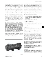
Страница 125: ...125 YORK INTERNATIONAL FORM 201 19 NM6 804 COMPRESSOR COMPONENTS CONT D FIG 68 COMPRESSOR COMPONENTS LD03669 7...

Страница 126: ...126 YORK INTERNATIONAL FORM 201 19 NM6 804 COMPRESSOR COMPONENTS CONT D FIG 69 COMPRESSOR COMPONENTS LD03670 Technical Data...

Страница 127: ...127 YORK INTERNATIONAL FORM 201 19 NM6 804 COMPRESSOR COMPONENTS CONT D FIG 70 COMPRESSOR COMPONENTS LD06079 MALE ROTOR RELIEF VALVE DISCHARGE CHECK VALVE 7...

Страница 128: ...EARING 22 BEARING CLAMP NUT 23 BEARING SPACER SLEEVE 24 BEARING PRELOAD SPRING 25 O RING 26 BEARING BORE PLUG 27 DISCHARGE COVER 28 BEARING BORE PLUG 29 BEARING PRELOAD SPRING 30 BEARING SPACER SLEEVE...

Страница 129: ...19 NM6 804 COMPRESSOR COMPONENTS CONT D FIG 72 COMPRESSOR COMPONENTS O RING MOTOR ROTOR MALE ROTOR LOCKING KEY MALE ROTOR FEMALE ROTOR O RING RELIEF VALVE ECONOMIZER PLUG SUPPORT RINGS LD03672 SLIDE V...

Страница 130: ...on the oil separator but do not tighten the flare nut on the delivery tubing With the bottom suction end of the pump submerged in oil to avoid entrance of air operate the pump until oil drips from th...

Страница 131: ..._____ Heat Recovery _______________________________ Sys 1 100 FLA _________________________Amps Sys 2 100 FLA _________________________Amps Sys 3 100 FLA _________________________Amps Sys 4 100 FLA __...

Страница 132: ...kPa Temp F C Liq Line Temp F C Subcooling F C Sys 1 Motor Protector Input ________________ Volts Sys 2 Motor Protector Input ________________ Volts Sys 3 Motor Protector Input ________________ Volts...

Страница 133: ...er economizer operation and motor cooling Correct superheat setting is approx 10 12 F 6 7 C The superheat is calculated as the difference between the pressure at the Economizer Service Valve on the co...

Страница 134: ...history data from recent safety shutdowns ON OFF ROCKER SWITCH This switch shuts down the entire chiller when placed in the OFF position The switch must be ON for the chiller to operate The systems wi...

Страница 135: ...nt systems are provided on the Mi croprocessor Board External interface is available for control of the chiller via a YORK ISN System or YORK Remote Control Center In addition EMS BAS System connectio...

Страница 136: ...f the time involved The battery is a 10 year lithium type but life will de pend upon whether the Real Time Clock s internal clock circuit is energized With the clock OFF a rated life of approximately...

Страница 137: ...ut Board which activates and de activates 115VAC control outputs to System 3 and 4 compressors solenoids etc These outputs are controlled in response to commands issued by the Microprocessor Board Rel...

Страница 138: ...the Motor Protector dip switches These switches are set at the factory according to motor specifications The module also provides phase rotation protection to as sure the screw compressor does not rot...

Страница 139: ..._ _ WHEN OFF AND SEGMENTS FLASH ONE AT A TIME IN A CIRCLE WHEN THE SYSTEM IS RUNNING ON NUMERICAL VALUES 29121A TOP VIEW TOP VIEW 29121A SIDE VIEW 29120A SWITCH PUSHED TO THE LEFT INDICATES ON SWITCHE...

Страница 140: ...input is used for purposes of demand limit and operates as follows Closing the input contact for a defined period of time allows reset of the Current Limit downward Contact closure of 1 11 seconds wil...

Страница 141: ...set Temp 4 sec 1 sec X 40 F 10 sec Reset Temp 120 Fsec 10 sec 12 F 6 C To determine the new setpoint add the reset to the setpoint programmed into memory In the example above if the programmed setpoin...

Страница 142: ...sable Jump Contact Real Time Clock and Battery Backup I C Microprocessor I C label shows version NOTE Dimple is positioned at top edge 3A Dip Switch Set 8 switches System Switches S2 System 1 S3 Syste...

Страница 143: ...els PHOTOGRAPH OF 50HZ MODEL LOGIC SECTION 00262VIP 1 2 3 6 7 5 4 8 ITEM 1 2 3 4 5 6 7 8 9 DESCRIPTION Microprocessor Board Back of Keypad I O Expansion Board 2 I O Expansion Board 1 Power Supply Boar...

Страница 144: ...SSOR HEATER CONTROL Each compressor has its own heater The heater will be off whenever the compressor is running As soon as the compressor shuts off the heater will turn on and stay on for 5 minutes A...

Страница 145: ...Individual system Run Status contacts are not available 1 21 LEAD LAG COMPRESSOR SELECTION The chiller may be set up for AUTO or MANUAL Lead Lag This is accomplished by programming the option under t...

Страница 146: ...ing at the TXV over 40 F 4 4 C This should not be confused with subcooling at the liquid valve which should generally be 12 Fto 15 F 6 7 C to 8 3 C The micro monitors the dif ference in pressure ratio...

Страница 147: ...147 YORK INTERNATIONAL FORM 201 19 NM6 804 8 This page intentionally left blank...

Страница 148: ...hese messages are described in detail below with ex amples of each display In each example is used as applicable to represent the system number where mes sages apply to individual systems 2 2 GENERAL...

Страница 149: ...id temperature is below the point where the microprocessor will bring the lead system on and or that the loading sequence has not loaded the chiller far enough to bring the lag system on The lag syste...

Страница 150: ...ressure nears the point at which the high pressure cutout would shut the system down When the above message appears discharge pressure has ex ceeded the programmable threshold and the compressor is be...

Страница 151: ...TO RE START ON POWER FAILURE is enabled Otherwise the chiller must be manually reset See Section 8 2 page 182 2 5 UNIT FAULT STATUS MESSAGES A Unit Fault will shut the entire chiller down when a prese...

Страница 152: ...s monitored to check that flow is present in the evaporator when a compressor is running Any external cycling devices fitted by the customer are connected in series with the flow switch YCAS chillers...

Страница 153: ...not be picked up by the High Oil Differential Safety since no flow will cause the dif ferential through the oil piping to drop to zero During normal operation differential oil pressure must be greater...

Страница 154: ...when the pilot solenoid is closed 10 times in 2 minutes due to low superheat S Y S H I G H M T R C U R R S Y S H I G H M T R C U R R The High Motor Current Safety protects against exces sively high m...

Страница 155: ...essor operation From this time the system will be shut down if average motor current is less than 10 of FLA Compressor Motor Protection Modules and Me chanical High Pressure Cutouts are integral to ea...

Страница 156: ...required data about the operation of the chiller This is particularly useful during commissioning mon itoring the operation of the chiller diagnosing potential future problems and service troubleshoot...

Страница 157: ...E M P 2 8 2 F S Y S O I L 1 7 6 P S I G S P 6 4 D P 1 9 5 P S I G S Y S O I L 1 5 7 4 F S T 3 1 0 D T 1 2 3 2 F S S A T S U C T 3 2 9 F S U C T S H E A T 1 5 0 F SlidevalvepositionisAPPROXIMATE and sh...

Страница 158: ...to programstheLowAmbient Cutout setting at 25 F 4 C and is not adjustable S 1 2 A M B I E N T C O N T R O L S T A N D A R D 3 5 MOTOR CURRENT KEY Pressing the Motor Current key displays compressor cur...

Страница 159: ...TION Incorrect programming may cause damage to the chiller Closed Place the switch in the CLOSED position selects the type of chiller as an air cooled chiller YCAS The switch MUST always be in the CLO...

Страница 160: ...tus message The following keys can be scrolled using the Function Key Chilled Liquid Temps System Data Motor Cur rent and Options Closed Placing the switch in the CLOSED position disables motor curren...

Страница 161: ...remotely as hard copy printouts The Operating Data Oper Data key provides a real time list of system operating data and programmed settings The History key provides a comprehensive list of op erating...

Страница 162: ...tor water pump and the status of the evaporator heater For the evaporator pump contacts ON contacts closed OFF contacts open The Evaporator Heater status is controlled on ambient temperature as follow...

Страница 163: ...printer attached In this case an example is shown for a YCAS 2 System Chiller YCAS 3 System models and YCAS 4 System models provide similar printouts for the appropriate number of systems YORK INTERNA...

Страница 164: ...the fault regardless of whether the fault caused a lockout to occur This information is not affected by power failures or manual resetting of a fault lockout The microprocessor stores data for up to...

Страница 165: ...5 0 P S I G D I S C H A R G E P R E S S U R E U N L O A D 3 7 5 0 P S I G S U C T I O N P R E S S U R E C U T O U T 4 4 0 P S I G S Y S 1 N O F A U L T S S Y S 2 H I G H M T R C U R R S 1 4 Y C A S Th...

Страница 166: ...This message indicates the status of both the evaporator pump signal from the microprocessor and the evapo rator heater This message indicates that a remote device such as a Remote Control Center an...

Страница 167: ...S I G S P 6 2 D P 2 7 1 P S I G S S A T S U C T 3 4 7 F S U C T S H E A T 1 0 5 F S S A T D S C H 1 2 9 F D S C H S H E A T 6 2 8 F S Y S S V S T E P 4 0 S Y S C O O L E R I N L E T R E F R I G T E M...

Страница 168: ...ENOID ON CONDENSER FAN STAGE 3 COMPRESSOR HEATER OFF WYE DELTA RELAY ON DAILY SCHEDULE S M T W T F S HOLIDAY MON START 00 00AM STOP 00 00AM TUE START 00 00AM STOP 00 00AM WED START 00 00AM STOP 00 00A...

Страница 169: ...e returned The Enter key is also used to scroll through available data when using the Program or Set Schedule Holiday keys 5 4 CANCEL KEY When the Cancel key is pressed the cursor will always return t...

Страница 170: ...lled liquid temperature and adjusts the chiller cooling capacity to maintain this temperature within a programmed range The capacity is controlled by switching compressors on or off and by varying a l...

Страница 171: ...eaving liquid temperature rises above the upper range limit of the Control Range the lead compressor will be started A 0VDC signal is sent to the compressor slide valve control solenoid to allow the i...

Страница 172: ...load continues to decrease the lead compressor will continue to unload to a slide valve position of 0 and will pump down and cycle off if the chilled liquid temperature drops below Setpoint Control R...

Страница 173: ...ed in the following table Percentage of Motor Current or Discharge Pressure Unload Point Maximum Steps of Unloading After Load Timer Counts to 0 100 1 102 2 104 3 106 4 108 5 115 10 In the case of Sat...

Страница 174: ...et Temperature Range key The following message will appear The display indicates the Remote Setpoint which is always equal to the chilled liquid setpoint programmed by the Chilled Liquid Temperature R...

Страница 175: ...isplay mode in which the cursor will disappear and the live clock will be displayed 7 CLOCK KEYS O U T O F R A N G E T R Y A G A I N 7 1 GENERAL The microprocessor features a continuously running in t...

Страница 176: ...are scrolled through by re petitively pressing the set Schedule Holiday key To re program any of the daily schedules key in the new Start time then if necessary change the associated AM PM by pressin...

Страница 177: ...n OFF period This key avoids the need to reprogram the Daily Schedule Once activated Manual Override is only active for a period of 30 minutes and the following status message will be observed M A N U...

Страница 178: ...down D I S C H A R G E P R E S S U R E C U T O U T 3 9 5 0 P S I G 8 PROGRAM KEY 8 1 GENERAL The Program key is used to program system operating parameters including cutout points for safeties antici...

Страница 179: ...r runs For the first 270 seconds of run ning suction pressure can be lower than the programmed cutout but must be greater than This cutout value increases with time until after 270 sec onds it equals...

Страница 180: ...mitations in the building See also Section 1 10 To program the Suction Pressure Cutout key in the re quired setting and press the Enter key to store the value into memory and scroll the next display H...

Страница 181: ...below the programmed limit The message will be removed and additional loading will take place when motor current drops below 90 of the programmed threshold Typically this setpoint should be set at 100...

Страница 182: ...utomatically program default values into memory This will preset all programmable values under the Program key to values that will allow operation of the chiller under most operating conditions This a...

Страница 183: ...25 0 F Ambient 3 9 Low 0 F 50 0 F 25 0 F Ambient 17 8 C 10 0 C 3 9 C Leaving Chilled Liquid Temp Cutout Water Cooling 36 0 2 2 Glycol Cooling 8 0 F 36 0 F 36 0 F 13 3 C 2 2 C 2 2 C Low Temp Glycol 5...

Страница 184: ...or software The superheat setpoint can be programmed on the control panel The purpose of the EEV is to meter a flow of liquid refrigerant into the evaporator to maintain a superheat FIG 79 ELECTRONIC...

Страница 185: ...that the 24VAC heat motor power signal is energized MOP FEATURE The controller also has an MOPfeature Maximum Op erating Pressure that overrides superheat control when the MOP setpoint is exceeded Th...

Страница 186: ...tdown This safety will lock out a system the first time and will not allow automatic restart ing Following are the messages for all systems OPERATING DATA DISPLAYS The following display relating to EE...

Страница 187: ...EV output will be set to 0 When the expansion valve type is set to electronic by closing DIP switch 7 the EEV controller low superheat safety device low superheat safety and the sensor failure safety...

Страница 188: ...out it is possible that the EEV has failed If the small charge in the bulb leaks the valve will not be able to open and the entire EEV must be replaced The system shuts down on Low Superheat Verify th...

Страница 189: ...t numbers relating to fans energized SYS 1 fan contactors are controlled by Relay Output Board 1 SYS 2 by Relay Output Board 2 SYS 3 is controlled by I O Expansion Board 2 TABLE 5 CONDENSER FAN CONTRO...

Страница 190: ...PSIG 195 PSIG 70 F 12M 13M 132 10 S 4 1 7 9 275 PSIG 205 PSIG 75 F 9M 12M 13M 130 132 10 15 5 3 5 7 9 285 PSIG 210 PSIG 80 F 10M 11M 12M 13M 131 132 10 14 1 6 1 3 5 7 9 295 PSIG 215 PSIG 85 F 9M 10M...

Страница 191: ...I O Expansion Board 2 FIG 81 CONDENSER FAN CONTROL LAYOUT FOR DXST COMPRESSORS UNITS LD05023 TABLE 7 CONDENSER FAN CONTROL AND FAN CONTACTOR DATA FOR DXST UNITS WITH 4 FANS SYSTEM At ambients above 8...

Страница 192: ...PSIG 70 F 29M 432 10 S 4 14 18 275 PSIG 205 PSIG 75 F 27M 29M 430 432 8 10 5 16 18 285 PSIG 210 PSIG 80 F 28M 29M 431 432 9 10 4 6 14 16 18 295 PSIG 215 PSIG 85 F 27M 28M 29M 430 431 432 8 9 10 At am...

Страница 193: ...Drop in Unit Type YCAS or YCWS Heat Recovery Unit Enabled or Disabled Sys 1 100 Full Load Amps 75 to 500 Amps Sys 2 100 Full Load Amps 75 to 500 Amps Sys 1 Motor Protector Input 1 0 to 5 0 volts Sys...

Страница 194: ...Phase 100 FLA Of Sys MP OL Value Set 0693 Sys 1 2 50 140 2 151 189 693 Sys 3 50 124 2 134 167 0773 Sys 1 2 50 140 2 151 189 0773 Sys 3 50 183 2 198 124 0783 Sys 1 2 50 124 2 134 167 0783 Sys 3 50 168...

Страница 195: ...A Of Sys MP OL Value Set 0693 Sys 1 2 50 140 2 151 189 693 Sys 3 50 124 2 134 167 0773 Sys 1 2 50 140 2 151 189 0773 Sys 3 50 183 2 198 143 0783 Sys 1 2 50 124 2 134 167 0783 Sys 3 50 168 2 181 132 08...

Страница 196: ...ample is shown below SERVICE MODE OUTPUT ENABLE The Service Mode allows the user to enable and disable the outputs except compressor To enter the Service Mode turn the UNIT switch off and press PROGRA...

Страница 197: ...conomizer TXV Solenoid Microboard Relay Board 1 J9 3 TB1 8 Sys 1 Wye Delta Relay Microboard Relay Board 1 J9 4 TB1 7 SPARE Microboard Relay Board 1 J9 5 TB1 6 5 Evaporator Heater Microboard Relay Boar...

Страница 198: ...oboard J15 8 Sys 1 Discharge Pressure Transducer Microboard J16 4 Sys 2 Suction Temp Sensor Microboard J16 6 Sys 1 Suction Temp Sensor Microboard J17 9 Input from I O Expansion Board Microboard J17 10...

Страница 199: ...board they are on TABLE 16 ANALOG OUTPUTS Microboard J4 1 Unit Switch Microboard J4 2 PWM Current Limit Microboard J4 3 SPARE Flow Switch Euro CAT only Microboard J4 4 PWM Temp Reset Microboard J4 5 S...

Страница 200: ...2 1 93 32 0 0 2 05 36 2 2 2 17 39 3 9 2 30 43 6 1 2 42 46 7 8 2 54 50 10 2 66 68 20 3 22 86 30 3 69 104 40 4 05 TEST POINT Test Point Microboard J11 9 3 8 12 SENSOR CALIBRATION CHARTS Pressure Transdu...

Страница 201: ...ero will be sent Tables 18 and 19 show the data values and page listings for this unit 8 13 ISN CONTROL TABLE 17 ISN RECEIVED DATA ISN CONTROL DATA PAGE P03 SETPOINT P04 ISN Current Limit P05 P06 P07...

Страница 202: ...URO CAT Sys 1 Heat Recovery Solenoid Status Heat Recovery P44 116 D Sys 1 Wye Delta P45 117 D Sys 2 Spare Sys 2 Discharge Cooling Solenoid Status Euro CAT Low Temp P46 118 D Sys 2 Liquid Line Solenoid...

Страница 203: ...58 161 A High Discharge Pressure Cutout P72 162 165 A Remote Leaving Chilled Liquid Setpoint P73 166 169 A Sys 1 Suction Superheat P74 170 173 A Cooling Range P75 174 177 A Sys 1 Discharge Superheat P...

Страница 204: ...ing 11 Anti Recycle Timer Active 11 High Oil Temperature 12 Manual Override 12 High Discharge Temperature 13 Suctioin Limiting 13 Improper Phase Rotation 14 Discharge Limiting 14 Low Motor Current MP...

Страница 205: ...205 YORK INTERNATIONAL FORM 201 19 NM6 804 8 This page intentionally left blank...

Страница 206: ...tions or ancillary equipment as applicable The Safety Section of this manual should be read carefully before at tempting any maintenance operations on the unit Daily Weekly Maintenance The following m...

Страница 207: ...ry between each minor and major service can vary depending on for instance application site conditions and expected operating schedule Normally a minor service should be carried out every three to six...

Страница 208: ...re Suction Temperature Suction Superheat Discharge Pressure Actual Discharge Temperature Oil Pressure Oil Temperature FLA Motor Oil Level example Oil Added gallons or liters Inlet Temperature Outlet T...

Страница 209: ...ooling1 X Check compressor and evaporator heaters for operation X Sample compressor oil and replace oil if necessary1 X Leak check the chiller1 X Disconnect power source and lock out Check tightness o...

Страница 210: ...condition of oil Check discharge superheat Evaporator Check water ow Check water pH glycol strength Check water pressure drop Check heater Air cooled condensers Check for air ow obstructions Brush ns...

Страница 211: ...YORK Sales and Service Center for information Please quote the unit model number and serial number When ordering spare parts we will require the following information to ensure the correct parts are...

Страница 212: ...displayed value is limit approximately correct The warning message should clear when the ambient air temperature rises above the programmed operating limit Check the programmed settings are correct f...

Страница 213: ...OIL PRESS DIFF is displyed High oil differential pressure Ball valve in oil circuit closed Dirty blocked oil lter Check ball valves are open position Check and change oil lter cartridge SYS LOW SUCTI...

Страница 214: ...the following costs and expenses 1 Labor to remove or reinstall any equipment materials or components 2 Shipping handling or transportation charges 3 Cost of refrigerant No warranty repairs or replace...

Страница 215: ...9 78 172 4 196 91 1 80 176 200 93 3 82 179 6 204 95 6 84 183 2 208 97 8 86 186 8 212 100 0 88 190 4 216 102 2 90 194 220 104 4 92 197 6 224 106 7 94 201 2 228 108 9 96 204 8 232 111 1 98 208 4 236 11...

Страница 216: ...1001 www york com P O Box 1592 York Pennsylvania USA 17405 1592 Subject to change without notice Printed in USA Copyright by York International Corporation 2004 ALL RIGHTS RESERVED Form 201 19 NM6 804...

Отзывы: