


133
YORK INTERNATIONAL
FORM 201.19-NM6 (804)
If equipped with an economizer, the
economizer will provide approxi-
mately an additional 20ºF (11.1ºC)
subcooling at the expansion valve in
ambients above 90ºF (32ºC). Below
90ºF (32ºC), the economizer will not
provide additional subcooling.
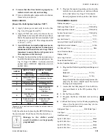
After the subcooling is set, the suction superheat should
be checked. The superheat should be checked only af ter
steady state operation of the chiller has been es tab lished,
the leaving water temperature has been pulled down to
the required leaving water temperature, and the unit is
running in a fully loaded condition. Correct su per heat
setting for a system is 10 - 12°F (6 - 7°C).
The superheat is calculated as the difference between
the actual temperature of the returned refrigerant gas in
the suction line entering the compressor and the tem-
per a ture corresponding to the suction pressure as shown
in a standard pressure/temperature chart.
Example:
Suction Temp = 46°F (8°C)
minus Suction Press
60 PSIG converted
to Temp - 34°F (1°C)
12°F (7°C)
The suction temperature should be taken 6" (13 mm)
be fore the compressor suction service valve, and the
suc tion pres sure is taken at the compressor suction
ser vice valve.
The EEV is non-adjustable. Super-
heat setpoint is programmable from
the keypad.
#
2. Record the suc tion tem per a ture, suction pres sure,
suction pressure con vert ed to tem per a ture, and
su per heat of each sys tem below:
CHECKING ECONOMIZER SUPERHEAT
(IF APPLICABLE) (15 TON TXV)
The economizer superheat should be checked to as sure
proper economizer operation and motor cooling. Cor rect
superheat setting is approx. 10 - 12°F (6 - 7°C).
The superheat is calculated as the difference between
the pressure at the Economizer Service Valve on the
com pres sor converted to the corresponding tem per a ture
in a standard pressure/temperature chart and tem per a ture
of the gas at the bulb on the entering piping to the mo-
tor housing.
Example:
Economizer Gas Temp = 90°F (32°C)
minus Economizer Press
139 PSIG converted
to Temp - 78°F (26°C)
12°F (6°C)
Normally, the thermal expansion valve need not be
ad just ed in the fi eld. If however, adjustment needs to
be made, the expansion valve adjusting screw should
be turned not more than one turn at a time, allowing
suf fi cient time (approximately 15 minutes) between
ad just ments for the system and the thermal expansion
valve to respond and settle out. Assure that superheat is
set between 10 - 12°F (6 - 7°C).
#
1. Record the motor gas temperature, econ o miz er
pres sure, economizer pressure con vert ed to
tem per a ture, and economizer su per heat below:
This superheat should only be checked
in an am bi ent above 90°F (32°C). Oth-
er wise, mid-range ad just ment (fac to ry
setting) is ac cept able. Below 90ºF
(32ºC) ambient, the economizer will
not provide additional subcooling.
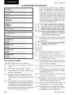
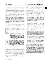
LEAK CHECKING
#
1. Leak check compressors, fi ttings, and pip ing to
as sure no leaks.
If the unit is functioning satisfactorily during the initial
operating period, no safeties trip and the compressors
load and unload to control water temperature, the chill er
is ready to be placed into operation.
7
SYS 1 SYS 2 SYS 3 SYS 4
Suction Temp =
PSIG
(kPa)
Suction Pess =
ºF
(ºC)
Temp =
ºF
(ºC)
Superheat =
ºF
(ºC)
SYS 1 SYS 2 SYS 3 SYS 4
Economizer Gas Temp =
PSIG
(kPa)
Economizer Press =
ºF
(ºC)
Temp =
ºF
(ºC)
Superheat =
ºF
(ºC)
Содержание YCAS
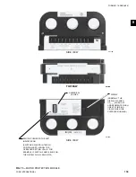
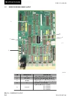
Страница 35: ...35 YORK INTERNATIONAL FORM 201 19 NM6 804 4 FIG 10 OPTION PANEL SECTION OPTION PANEL LAYOUT TYPICAL 00246VIP...
Страница 43: ...43 YORK INTERNATIONAL FORM 201 19 NM6 804 5 This page intentionally left blank...
Страница 45: ...45 YORK INTERNATIONAL FORM 201 19 NM6 804 6 This page intentionally left blank...
Страница 65: ...65 YORK INTERNATIONAL FORM 201 19 NM6 804 7 LD09359 Electronic Panel 035 19205 104 Rev A...
Страница 79: ...79 YORK INTERNATIONAL FORM 201 19 NM6 804 LD09376 FIG 40 CONNECTION DIAGRAM 4 COMPRESSOR Power Panel...
Страница 81: ...81 YORK INTERNATIONAL FORM 201 19 NM6 804 LD09378 CONNECTION WIRING DIAGRAM Electronic Panel...
Страница 83: ...83 YORK INTERNATIONAL FORM 201 19 NM6 804 FIG 43 CONNECTION DIAGRAM 4 COMPRESSOR LD09380 Power Panel...
Страница 91: ...91 YORK INTERNATIONAL FORM 201 19 NM6 804 This page intentionally left blank...
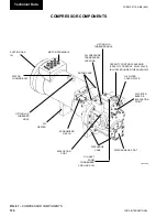
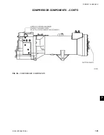
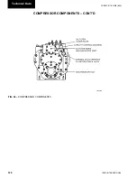
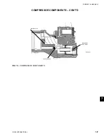
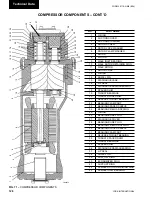
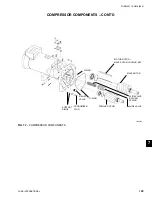
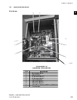
Страница 125: ...125 YORK INTERNATIONAL FORM 201 19 NM6 804 COMPRESSOR COMPONENTS CONT D FIG 68 COMPRESSOR COMPONENTS LD03669 7...
Страница 147: ...147 YORK INTERNATIONAL FORM 201 19 NM6 804 8 This page intentionally left blank...
Страница 205: ...205 YORK INTERNATIONAL FORM 201 19 NM6 804 8 This page intentionally left blank...