


11
YORK INTERNATIONAL
FORM 201.19-NM6 (804)
Electrical
The unit must be grounded. No in stal la tion or main-
te nance work should be attempted on the
electrical
equip ment without fi rst switching OFF, isolating and
lock ing-off the power supply. Work on live equipment
must only be carried out by suitably trained and qualifi ed
per son nel. No attempt should be made to gain access to
the con trol panel or electrical enclosures during nor mal
op er a tion of the unit.
Rotating Parts
Fan guards must be fi tted at all times and not removed
unless the power supply has been isolated. If ductwork is
to be fi tted, requiring the wire fan guards to be re moved,
alternative safety measures must be taken to protect
against the risk of injury from rotating fans.
Sharp Edges
The fi nning on the air cooled con dens er coils has sharp
metal edges. Reasonable care should be taken when
working in contact with the coils to avoid the risk of
mi nor abra sions and lac er a tions. The use of gloves is
recommended.
Refrigerants and Oils
Refrigerants and oils used in the unit are generally non-
toxic, non-fl ammable and non-corrosive, and pose no
spe cial safety hazards. Use of gloves and safety glass es
are, however, recommended when working on the unit.
The build up of refrigerant vapor, from a leak for ex-
am ple, does pose a risk of asphyxiation in confi ned or
enclosed spac es and attention should be given to good
ven ti la tion.
High Temperature and Pressure Cleaning
High temperature and pressure cleaning methods (e.g.
steam cleaning) should not be used on any part of the
pressure system as this may cause operation of the pres-
sure relief device(s). Detergents and solvents which may
cause corrosion should also be avoided.
EMERGENCY SHUTDOWN
In case of an emergency the electrical option panel is
fi t ted with an emergency stop switch CB4 (3 System)
or CB5 (4 System) located in the bottom right of the
Microprocessor Panel. Separate Circuit Break ers, CB1
(Sys tem 1), CB2 (Sys tem 2), CB3 (Sys tem 3) or CB4
(Sys tem 4) can also be used to stop the re spec tive sys tem
in an emer gen cy. When op er at ed, CB4 re moves the
elec tri cal supply from the con trol sys tem, thus shut ting
down the unit.
1
Содержание YCAS
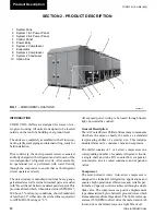
Страница 35: ...35 YORK INTERNATIONAL FORM 201 19 NM6 804 4 FIG 10 OPTION PANEL SECTION OPTION PANEL LAYOUT TYPICAL 00246VIP...
Страница 43: ...43 YORK INTERNATIONAL FORM 201 19 NM6 804 5 This page intentionally left blank...
Страница 45: ...45 YORK INTERNATIONAL FORM 201 19 NM6 804 6 This page intentionally left blank...
Страница 65: ...65 YORK INTERNATIONAL FORM 201 19 NM6 804 7 LD09359 Electronic Panel 035 19205 104 Rev A...
Страница 79: ...79 YORK INTERNATIONAL FORM 201 19 NM6 804 LD09376 FIG 40 CONNECTION DIAGRAM 4 COMPRESSOR Power Panel...
Страница 81: ...81 YORK INTERNATIONAL FORM 201 19 NM6 804 LD09378 CONNECTION WIRING DIAGRAM Electronic Panel...
Страница 83: ...83 YORK INTERNATIONAL FORM 201 19 NM6 804 FIG 43 CONNECTION DIAGRAM 4 COMPRESSOR LD09380 Power Panel...
Страница 91: ...91 YORK INTERNATIONAL FORM 201 19 NM6 804 This page intentionally left blank...
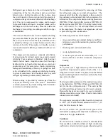
Страница 125: ...125 YORK INTERNATIONAL FORM 201 19 NM6 804 COMPRESSOR COMPONENTS CONT D FIG 68 COMPRESSOR COMPONENTS LD03669 7...
Страница 147: ...147 YORK INTERNATIONAL FORM 201 19 NM6 804 8 This page intentionally left blank...
Страница 205: ...205 YORK INTERNATIONAL FORM 201 19 NM6 804 8 This page intentionally left blank...