


75
YORK INTERNATIONAL
FORM 201.19-NM6 (804)
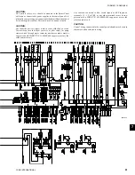
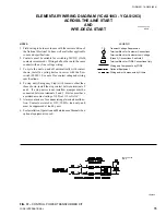
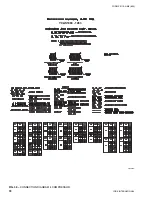
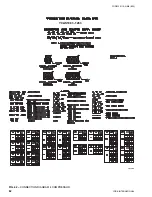
NOTES:
1. Field wiring to be in accordance with the current edi tion of
the National Electrical Code as well as all oth er ap pli ca ble
codes and specifi cations.
2. Contacts must be suitable for switching 24VDC, (Gold
contacts recommend). Wiring shall not be run in the same
conduit with any line voltage wiring.
3. To cycle the unit on and off automatically with contact
shown, install a cycling device in series with the fl ow
switch (FLSW). See note 2 for contact rating and wiring
specifi cations.
4. To stop unit (Emergency Stop) with contacts other than
those shown, install the stop contact between terminals 5
and 1. If a stop device is not installed, a jumper must be
connected between terminals 5 and 1. Device must have
a minimum contact rating of 100A at 115 volts A.C.
5. Alarm contacts are for annunciating alarm/unit malfunc-
tion. Contacts are rated at 115V, 100VA, load only, and
must be suppressed at load by user.
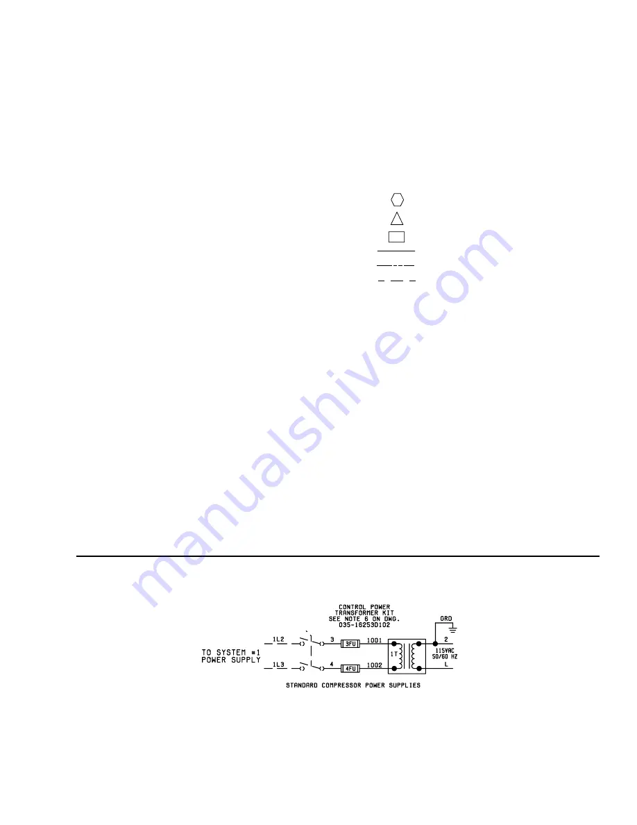
6. See Installation, Operation and Maintenance Manual when
optional equipment is used.
LEGEND
Transient Voltage Suppression
Terminal Block for Customer Connections
Terminal Block for Customer Low Voltage
(Class 2) Connections. See Note 2
Terminal Block for YORK Connections Only
Wiring and Components by YORK
Optional Equipment
Wiring and/or Components by Others
T S
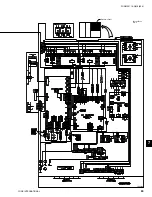
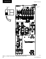
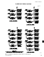
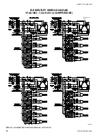
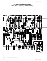
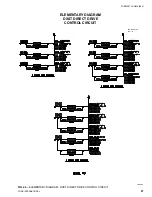
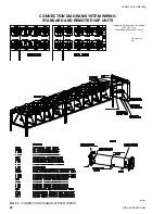
ELEMENTARY WIRING DIAGRAM (YCAS1063 - YCAS1263)
ACROSS-THE-LINE START
AND
WYE-DELTA START
LD09368
FIG. 37
–
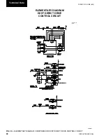
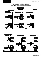
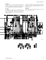
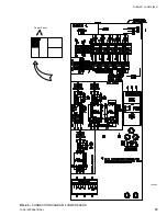
CONTROL POWER TRANSFORMER KIT
035-16253-103
Rev - A
035-16253-102
REV B
Содержание YCAS
Страница 35: ...35 YORK INTERNATIONAL FORM 201 19 NM6 804 4 FIG 10 OPTION PANEL SECTION OPTION PANEL LAYOUT TYPICAL 00246VIP...
Страница 43: ...43 YORK INTERNATIONAL FORM 201 19 NM6 804 5 This page intentionally left blank...
Страница 45: ...45 YORK INTERNATIONAL FORM 201 19 NM6 804 6 This page intentionally left blank...
Страница 65: ...65 YORK INTERNATIONAL FORM 201 19 NM6 804 7 LD09359 Electronic Panel 035 19205 104 Rev A...
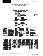
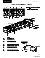
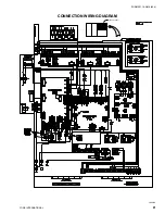
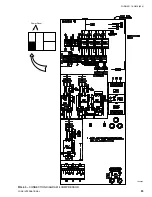
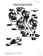
Страница 79: ...79 YORK INTERNATIONAL FORM 201 19 NM6 804 LD09376 FIG 40 CONNECTION DIAGRAM 4 COMPRESSOR Power Panel...
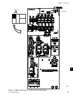
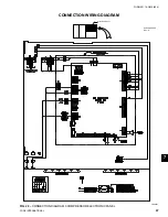
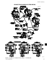
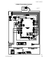
Страница 81: ...81 YORK INTERNATIONAL FORM 201 19 NM6 804 LD09378 CONNECTION WIRING DIAGRAM Electronic Panel...
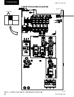
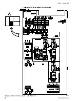
Страница 83: ...83 YORK INTERNATIONAL FORM 201 19 NM6 804 FIG 43 CONNECTION DIAGRAM 4 COMPRESSOR LD09380 Power Panel...
Страница 91: ...91 YORK INTERNATIONAL FORM 201 19 NM6 804 This page intentionally left blank...
Страница 125: ...125 YORK INTERNATIONAL FORM 201 19 NM6 804 COMPRESSOR COMPONENTS CONT D FIG 68 COMPRESSOR COMPONENTS LD03669 7...
Страница 147: ...147 YORK INTERNATIONAL FORM 201 19 NM6 804 8 This page intentionally left blank...
Страница 205: ...205 YORK INTERNATIONAL FORM 201 19 NM6 804 8 This page intentionally left blank...


