


64
| Working with the V-Line Module | SmartNA-X 1G/10G Modular
SmartNA-X
™
1G/10G User Guide 1.4
©
2015 Network Critical Solutions Limited
Configuring the V-Line operational mode
Depending on how you want to integrate your network tools into the TAP, V-Line Modules can be configured to operate
in V-Line mode, Breakout mode, Aggregation mode, or Egress mode.
Configure V-Line mode
1.
Click on the V-Line module you wish to configure and select the
V-Line
tab.
2.
From
V-Line mode
, select
V-Line
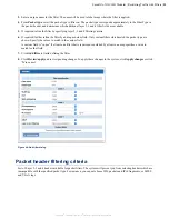
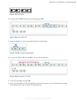
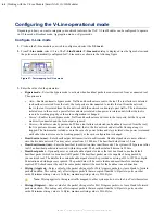
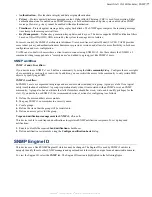
. The
V-Line Module: V-Line mode
dialog is displayed (see the figure below) and
the ports are automatically configured for V-Line mode, as shown in the following figure.
Figure 57: Port mapping for V-Line mode
3.
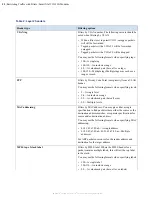
Enter the values for the parameters:
•
Bypass mode
—Select the bypass mode to activate when heartbeat packets are not received from a connected tool.
The options are:
•
Auto
—Enables automatic bypass mode. Traffic and heartbeats are sent to the tool. If a tool failure is detected
(no heartbeats received from the tool), the tool ports are disconnected to isolate the tool from the network;
that is, the tool is isolated from the live network with the network continuing to pass traffic. The tool remains
isolated even in the case of a power failure and stays isolated when power is returned until either the tool is
seen to be working properly or the card configuration is changed
•
Forced
—Enables forced bypass mode. Traffic and heartbeats are still sent to the tool ports, but the live ports
are directly connected and the tool output is ignored.
•
Reverse
—Enables reverse bypass mode. When a tool failure is detected (no heartbeats received from the tool),
the live ports are disconnected to isolate the link; that is, the live network and all traffic flowing along it is
stopped. The link remains isolated even in the case of a power failure and stays isolated when power is returned
until either the tool is seen to be working properly or the card configuration is changed.
•
Heartbeat rate (ms)
—Enter heartbeat packet transmit rate in milliseconds. Heartbeat packets are never allowed
onto the live data network. You may enter values from 1–1000 ms. The heartbeat default rate is 50 ms.
•
Heartbeat timeout (ms)
—Enter the heartbeat loss detection time in milliseconds. The system will bypass an inline
tool if no heartbeat packets are received within this period. The heartbeat default timeout is 250 ms.
•
Heartbeat packet
—Optionally enter a custom heartbeat packet or leave the text box blank to use the default
heartbeat packet, which is a broadcast ARP packet. The heartbeat packet
must
be capable of being passed by
your network tool. The data for the custom heartbeat packet must be provided as a string of 32 to 3072 hex digits.
Punctuation and whitespace are ignored. The packet data will be sent verbatim and must therefore include any
required FCS checksum at the end. The same packet data will be used for the heartbeat in each direction.
•
Slicing (A ingress)
—Enter a value for the packet slicing size for Port A ingress packets, or leave blank to forward
packets unsliced. This setting only affects ingress packets that are copied from the A/B ports to ports on other
cards. Minimum slicing value is 16 Bytes, maximum slicing value is 9216 Bytes.
Note:
Slicing applies to the ingress traffic mapped to other system ports, not to the Live Ports themselves.
•
Slicing (B ingress)
—Enter a value for the packet slicing size for Port B ingress packets, or leave blank to forward
packets unsliced. This setting only affects ingress packets that are copied from the A/B ports to ports on other
cards. Minimum slicing value is 16 Bytes, maximum slicing value is 9216 Bytes.