


SmartNA-X 1G/10G Modular | Introduction |
17
SmartNA-X
™
1G/10G User Guide 1.4
©
2015 Network Critical Solutions Limited
1.
Connect your live network to TAP ports
A
and
B
. If you are connecting to a 10G network, you must connect to the AB
ports of a 10G module fitted in slot 1 of the chassis. If connecting to a 1G network, you may use any of the
AB
ports,
including those in slot 1.
Verify that the LED link lights are on. If there is no link, you may need to reconfigure the port comm settings. See the
relevant step below.
2.
Map ports
A
and
B
to each other to join the live links and allow traffic to flow across the TAP.
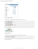
Figure 7: Map A and B ports to join the live links
Assuming module 3, the equivalent CLI commands are:
CONTROLLER>
set map 3a to 3b
CONTROLLER>
set map 3b to 3a
3.
Map the live ports to output ports
C
and/or
D
as required.
Figure 8: Map A and B ports to C and/or D output ports
The equivalent CLI commands are as follows:
CONTROLLER>
set map 3a to 3c
CONTROLLER>
set map 3b to 3c
4.
Configure port usage and for copper ports, communication settings. In most cases, copper port settings can be left at
Auto, in which case the linked ports will negotiate the optimum settings themselves.