


20
| Getting Started | SmartNA-X 1G/10G Modular
SmartNA-X
™
1G/10G User Guide 1.4
©
2015 Network Critical Solutions Limited
5.
Depending on whether your chassis is AC or DC powered, plug the chassis into an AC (100V-240V) or a DC (-42V to
-63V) supply. If your chassis has dual power sockets, make sure they are connected to
independent
supplies to ensure
the chassis is able to remain powered should either suffer a power cut.
6.
Turn on the chassis power switch(es) to start the system. Management interfaces will be available within two minutes,
but data ports will immediately begin to pass traffic.
7.
Connect management cables to the management ports, as described in
Cabling for administrative connections
on page
20.
Installing the TAP modules
TAP modules are hot-swappable and can be installed and removed while the chassis is powered up without affecting other
modules. Red 10G bps modules must only be installed in the left-most slot (Slot 1). Blue 1G bps modules may be installed
in any slot (Slots 1–4).
1.
Wear an anti-static wrist strap or take other precautions against electrostatic discharge (ESD) before handling the TAP
modules.
2.
Remove the TAP modules from their ESD bags. The modules are colour-coded as follows:
• Red – 10G bps maximum. Red modules must only be used in Slot 1 (left-most slot).
• Blue – 1G bps maximum. Blue modules may be used in any slot.
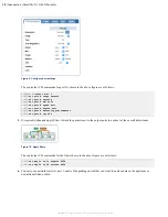
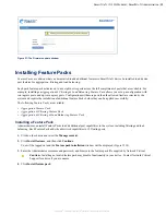
The following figure shows the correct placement of the 10G and 1G modules:
3.
Carefully slide the TAP modules into the chassis slots until they are fully inserted and flush with the chassis face. You
should feel a slight resistance as the module engages with contacts in the chassis. Note that red modules can only be
used in Slot 1, as shown in the figure below.
Figure 12: Install red 10G Modules in Slot 1 only
4.
Fit the supplied blanking plates to any remaining empty slots. This is to ensure correct cooling of the chassis during
operation.
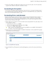
Cabling for administrative connections
SmartNA-X provides dual administration ports for networked or serial access to the management interfaces. In most
cases, users will connect to the system remotely over a network. When first setting up, you may need to use the
CONSOLE in order to configure the network interface address.
SmartNA-X provides the following administration ports: