NetApp NearStore R100 Скачать руководство пользователя страница 61

Chapter 4: Powering On an R100 System

51


Connecting the system to a power source and powering on

Connecting the chassis to AC power

Connecting the 
R100 chassis to AC 
power

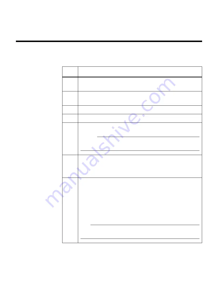
To connect the chassis to an AC power source, complete the following steps.

Step

Action

1

Confirm that the power switch on each power supply is in the Off (0) 
position.

2

Connect the socket end of the supplied power cord to the recessed 
power plug on the power supply.

3

Secure the power cord with the retaining clip on the power supply.

4

Plug the other end of the power cord into a grounded electrical outlet.

5

Repeat Steps 1 through 4 for the second power supply. 

Caution

To obtain power supply redundancy, make sure that you connect the 
second power supply to a separate AC circuit.

6

Turn the power switch on the power supplies to the On (l) position.

Result: 

The system verifies the hardware and loads the operating 

system.

7

Make sure that the following LEDs illuminate:

Front panel LEDs

Power supply LEDs

Network port LEDs

The LED responses are described in “

Chassis LED responses at 

startup

” on page 54.

Note

If the LEDs do not illuminate, contact Network Appliance Technical 
Support.

Содержание NearStore R100

Страница 1: ...Appliance Inc 495 East Java Drive Sunnyvale CA 94089 USA Telephone 1 408 822 6000 Fax 1 408 822 4501 Support telephone 1 888 4 NETAPP Documentation comments doccomments netapp com Information Web htt...

Страница 2: ...ered trademarks of Network Appliance Inc in the United States and other countries Network Appliance is a registered trademark of Network Appliance Inc in Monaco and a trademark of Network Appliance In...

Страница 3: ...stalling an R100 disk shelf using the four post rail kit 19 Installing an R100 chassis 21 Chapter 3 Connecting an R100 System 25 Connecting an R100 disk shelf 26 Connecting a disk shelf using a dual p...

Страница 4: ...k Shelf Devices 69 Replacing a disk shelf in a rack 70 Removing a disk shelf from the R100 rack 71 Replacing a disk in a disk shelf 72 Removing a disk from a disk shelf 73 Installing a disk in a disk...

Страница 5: ...Replacing the LED LCD subassembly 119 Replacing the CompactFlash unit subassembly 122 Replacing the CompactFlash card 123 Replacing the CompactFlash card reader subassembly 125 Chapter 9 Troubleshooti...

Страница 6: ...vi Table of Contents...

Страница 7: ...ity with accepted tools and procedures for installing and operating sensitive electronic equipment Terminology This guide uses the following terms R100 or R100 system refers at a minimum to an R100 ch...

Страница 8: ...ype of information Italic type Words or characters that require special attention File names and path names Placeholders for information you must supply For example if the guide says to enter the arp...

Страница 9: ...isolated branch circuits To reduce the risk of personal injury or equipment damage allow internal components time to cool before touching them and ensure that the equipment is properly supported or b...

Страница 10: ...und isolierte Abzweigleitungen angeschlossen sein Zum Schutz vor K rperverletzung oder Sachsch den am Ger t lassen Sie die inneren Bauteile stets vor dem Ber hren abk hlen Sorgen Sie daf r dass das Ge...

Страница 11: ...lists of required tools and equipment and rules for the installation of the storage system Note This guide does not provide the process for configuring your new storage system However it does provide...

Страница 12: ...ack installation R100 user manuals Required tools To install the storage system components in an equipment rack you need the following tools and equipment Phillips screwdrivers 0 1 and 2 10 32 steel s...

Страница 13: ...The following table lists documentation you might need to help manage the storage system Document name When to use Site Requirements Guide Use this guide to assist you in preparing your site for your...

Страница 14: ...ves Freestanding equipment rack requirements The freestanding equipment rack must meet the following requirements A width of 19 inches 48 26 cm Front installation rails compliant with EIA standard EIA...

Страница 15: ...he AC power electrical requirements for the chassis Characteristics U S Metric Height 8 75 in or 5U where 1U 1 75 in 22 2 cm Width 17 in 43 2 cm Depth 25 25 in 64 1 cm Weight fully loaded 66 lbs 30 kg...

Страница 16: ...and electrical information see the Site Requirements Guide Inrush current 40A maximum at 110V AC per power supply 50A maximum at 220V AC per power supply Frequency 50 to 60 Hz Power Rating Watts 300 m...

Страница 17: ...ch disk shelf Characteristics U S Metric Height 7 0 in or 4U where 1U 1 75 in 17 8 cm Width 17 in 43 2 cm Depth 22 0 in 55 9 cm Weight fully loaded 55 lbs 25 kg Condition Requirement Power input 115 2...

Страница 18: ...rical requirements for the entire R100 system The following table lists the AC power electrical requirements for the entire R100 system Power Rating Current 7A steady state 180V AC 14A steady state 12...

Страница 19: ...t least one other person when you install the chassis in the rack Rules for arranging the components in the rack Observe the following rules when arranging the components in a rack for an R100 storage...

Страница 20: ...10 Installation rules and restrictions...

Страница 21: ...System About this chapter This chapter provides all the information you need to install an R100 system into a rack Topics in this chapter This chapter describes the following topics Installing an R100...

Страница 22: ...rmation you need to install an R100 disk shelf into a rack Topics in this section This section describes the following topics Before you begin your installation on page 13 Installing an R100 disk shel...

Страница 23: ...ing Disk drive labeling Each disk drive is labeled with a unique SCSI address which helps define its location within the disk shelf Addresses are assigned to each drive bay beginning right to left in...

Страница 24: ...f the disk shelf Enclosure services conditions are communicated to the chassis through the EMU module The following table describes the three stages of enclosure services monitoring 4 5 6 7 are reserv...

Страница 25: ...r mount the R100 into a Telco type rack without Telco support brackets the R100 disk shelf will collapse from the rack under its own weight Step Action 1 Put on the antistatic wrist strap and groundin...

Страница 26: ...to which you want to attach the brackets and secure the brackets with the 10 Phillips head screws 2 Align the holes on the rack to the holes on the bracket and secure the disk shelf to the rack with...

Страница 27: ...the rack steady 2 Insert the mounting screws through the two inner holes of the mounting bracket Tighten the screws so that the mounting bracket is firmly attached to the Telco rack Repeat for the opp...

Страница 28: ...the rack mount kit 7 Repeat the disk shelf installation for each disk shelf until four disk shelves are installed together from the bottom of the rack 8 Go to Installing an R100 chassis on page 21 for...

Страница 29: ...post rail kit Installing the disk shelf To install the R100 disk shelf using the four post rail kit complete the following steps using the illustration for reference 3 4 5 1 2 M5 x 10 screws 1 8 Lock...

Страница 30: ...he rear post using two M5 x 10 screws washers and lock washers then tighten the rail and support 4 Repeat Steps 1 through 3 for the right support rail 5 Install the clip nuts for the disk shelf into t...

Страница 31: ...rack you must install the equipment from the bottom up to ensure the greatest stability Front installed position The installation brackets lie flush with the chassis front panel The chassis is shipped...

Страница 32: ...ving the installation brackets If you want to mid install the chassis in a rack you must move the installation brackets on the sides of the chassis from the default position To move the installation b...

Страница 33: ...nstallation bracket holes with the chassis holes 4 Attach each installation bracket to the chassis by inserting screws into the bracket and chassis holes and tightening the screws Step Action Installa...

Страница 34: ...ter the chassis is attached by the bottom screws You do not need another person to hold the chassis from the back of the rack after fastening these screws 5 Insert and tighten the remaining screws 6 F...

Страница 35: ...hapter describes how to connect an R100 system Topics in the chapter This chapter provides information about the following topics Connecting an R100 disk shelf on page 26 Connecting an R100 chassis to...

Страница 36: ...or single port SCSI adapter cards to connect the disk shelves to the chassis Topics in this section For details about connecting a disk shelf to the R100 chassis see the following topics Connecting a...

Страница 37: ...10 100 BASE T PS2 CAUTION PROPERLY SHUT DOWN SYSTEM BEFORE OPENING CHASSIS OPENING WITH POWER ON WILL CAUSE IMPROPER SHUTDOWN MAC 00 A0 98 00 00 01 Console Diagnostic SWITCH P S OFF PRIOR TO REMOVAL I...

Страница 38: ...VHDCI 68P as shown in the following illustration 94 264VAC 8A MAX 50 80HZ 94 264VAC 8A MAX 50 80HZ EXT 1 EMU EXT 2 AUX LCD FAN 1 FAN 2 FAN 3 PS1 10 100 BASE T PS2 CAUTION PROPERLY SHUT DOWN SYSTEM BE...

Страница 39: ...nce shown in the following illustration PS1 10 100 BASE T PS2 CAUTION PROPERLY SHUT DOWN SYSTEM BEFORE OPENING CHASSIS OPENING WITH POWER ON WILL CAUSE IMPROPER SHUTDOWN MAC 00 A0 98 00 00 01 Console...

Страница 40: ...SCSI LVD VHDCI 68P as shown in the following illustration 94 264VAC 8A MAX 50 80HZ 94 264VAC 8A MAX 50 80HZ EXT 1 EMU EXT 2 AUX LCD FAN 1 FAN 2 FAN 3 PS1 10 100 BASE T PS2 CAUTION PROPERLY SHUT DOWN...

Страница 41: ...o twisting or bending of the connectors at the connection points Excessive bending and twisting might damage components within the chassis or to the cables 2 After making the connections use cable tie...

Страница 42: ...on Step Action 94 264VAC 8A MAX 50 80HZ 94 264VAC 8A MAX 50 80HZ EXT 1 EMU EXT 2 AUX LCD FAN 1 FAN 2 FAN 3 94 264VAC 8A MAX 50 80HZ 94 264VAC 8A MAX 50 80HZ EXT 1 EMU EXT 2 AUX LCD FAN 1 FAN 2 FAN 3 9...

Страница 43: ...ices Use a cable that is Appropriate to the tape adapter installed in your chassis Of an approved length for the third party device Note See the documentation for the third party device Check the Syst...

Страница 44: ...tape backup device See the documentation for the tape backup device 2 If you have a robotic loader on the tape backup device or a Fibre Channel switch set its ID 3 Turn off all third party devices and...

Страница 45: ...with an active SCSI terminator For information about terminating the open port see the documentation for the tape backup device 6 Go to Connecting an R100 chassis to an Ethernet network on page 38 St...

Страница 46: ...third party documentation about connecting the Fibre Channel tape backup device to the Fibre Channel switch Step Action 1 Set the ID on the Fibre Channel switch See the documentation for the Fibre Ch...

Страница 47: ...annel switch 5 Clip and click in each end of the cable 6 Go to Connecting an R100 chassis to an Ethernet network on page 38 Step Action PS1 10 100 BASE T PS2 CAUTION PROPERLY SHUT DOWN SYSTEM BEFORE O...

Страница 48: ...ections supported by your R100 chassis and how to connect to each type of Ethernet connection For detailed information For details about connecting an R100 chassis to an Ethernet network see the follo...

Страница 49: ...ed slot locations for additional NICs SCSI shelf adapter cards NVRAM III card and backup device dual port SCSI adapter configuration shown Note For specific information about the slot assignments avai...

Страница 50: ...thernet port Cabling requirements 10Base T 100Base TX Category 3 10Base T only or 5 10Base T 100Base TX unshielded twisted pair UTP cable with RJ 45 connectors 100Base TX 1000Base T Category 5 unshiel...

Страница 51: ...pper cabling To connect the chassis to a 10Base T 100Base TX or 100Base TX 1000Base T Ethernet network using copper cabling complete the following step Step Action 1 If your Ethernet port is Then The...

Страница 52: ...port on the NIC until it clicks and locks into place The following illustration shows a UTP cable with an RJ 45 connector connecting to a single port 100Base TX 1000Base T NIC Note The NIC is labeled...

Страница 53: ...se SX fiber port Connecting to a 1000Base SX fiber port To connect the chassis to a 1000Base SX network using fiber complete the following step Step Action 1 Push the cable with the SC connector into...

Страница 54: ...44 Connecting an R100 chassis to an Ethernet network...

Страница 55: ...pter describes how to establish a console connection to the chassis and how to power on the system Topics in this chapter This chapter describes the following topics Connecting the chassis to an ASCII...

Страница 56: ...the display length is set to 25 lines ASCII terminal console cable wiring The ASCII terminal console is connected to the chassis with a DB 9 serial cable through the serial port on the back of the cha...

Страница 57: ...arameter Setting Baud 9600 Data bit 8 Parity None Stop bits 1 Flow control None Note See your terminal documentation for information about changing your ASCII console terminal settings 2 Connect the D...

Страница 58: ...require time to power on reset and prepare to respond to the chassis The chassis expects these units to be ready for input output when it powers on and performs its reset and self test Power on proce...

Страница 59: ...PSU1 into the power receptacle on the right connector rear view 3 Plug the power cord for PSU2 into the power receptacle on the left connector rear view 4 Plug the other end of each power cord into s...

Страница 60: ...n 7 Make sure that the following LEDs illuminate Front panel LEDs Power supply LEDs The LED responses are described in Disk shelf LED responses at startup on page 61 Note If the LEDs do not illuminate...

Страница 61: ...ning clip on the power supply 4 Plug the other end of the power cord into a grounded electrical outlet 5 Repeat Steps 1 through 4 for the second power supply Caution To obtain power supply redundancy...

Страница 62: ...essages are described in System messages at startup on page 63 Note If the startup messages do not appear contact Network Appliance Technical Support 9 Go to the Getting Started Guide to install softw...

Страница 63: ...include The LED responses from the various hardware components on the chassis The LED responses from the various hardware components on the disk shelf The system messages displayed on The chassis LCD...

Страница 64: ...on describes the LED responses from the chassis and various hardware components on the chassis at startup For detailed information For details about chassis LED responses at startup see the following...

Страница 65: ...on shows the LEDs on the front panel of an R100 chassis Description of front panel LEDs The following table describes the three LEDs on the front panel NetApp R100 activity status power Activity Statu...

Страница 66: ...you turn on the chassis and stays lit while the operating system is loading Note If the Status LED remains amber a fault occurred or the system halted The chassis LCD identifies the reason for this c...

Страница 67: ...n of LEDs The following illustration shows the AC power supply LEDs on the back panel Description of LEDs The following table describes the AC power supply LEDs LED State of illumination Explanation A...

Страница 68: ...TX 1000Base T NIC LEDs on page 59 1000Base SX fiber NIC LEDs on page 60 Onboard 10Base T 100Base TX Ethernet port LEDs Location of LEDs The onboard 10Base T 100Base TX Ethernet port has two LEDs as sh...

Страница 69: ...ollowing table describes the LEDs on the 100Base TX 1000Base T NIC LEDs State Indicates Top not labeled N A Not used LNK On Valid network connection For some devices the LED can take several seconds t...

Страница 70: ...ollowing illustration Note The R100 chassis uses only the TX RX and LINK LEDs Description of LEDs The following table describes the LEDs on the 1000Base SX fiber NIC LED State Indicates TX On Transmit...

Страница 71: ...ses the types and functions of each LED on the front of the disk shelf Location of LEDs The disk shelf LEDs are displayed on the front side of the disk shelf as shown in the following illustration sys...

Страница 72: ...unication failure between the chassis and the disk shelf Off Disk shelf is connected and is communicating with the chassis power On yellow Disk shelf is powered on Off Disk shelf is powered off drive...

Страница 73: ...Programmable Read Only Memory The following is an example of the POST messages that appear on the system console of an R100 Header Intel Open Firmware by FirmWorks Copyright 1995 2001 FirmWorks Netwo...

Страница 74: ...GAK8 136 0GB 320163048 512B sect 1 Maxtor 4G160J8U66 GAK8 136 0GB 320163048 512B sect 2 Maxtor 4G160J8U66 GAK8 136 0GB 320163048 512B sect 3 Maxtor 4G160J8U66 GAK8 136 0GB 320163048 512B sect 8 Maxto...

Страница 75: ...r 4G160J8U66 GAK8 136 0GB 320163048 512B sect 0 Maxtor 4G160J8U66 GAK8 136 0GB 320163048 512B sect 9 Maxtor 4G160J8U66 GAK8 136 0GB 320163048 512B sect 15 Maxtor 4G160J8U66 GAK8 136 0GB 320163048 512B...

Страница 76: ...048 512B sect 1 Maxtor 4G160J8U66 GAK8 136 0GB 320163048 512B sect 8 Maxtor 4G160J8U66 GAK8 136 0GB 320163048 512B sect 2 Maxtor 4G160J8U66 GAK8 136 0GB 320163048 512B sect 9 Maxtor 4G160J8U66 GAK8 13...

Страница 77: ...n an R100 System 67 12 Maxtor 4G160H8U66 GAK8 136 0GB 320163048 512B sect Shelf 0 R100Shelf EMU rev 0829 Bridge firmware rev N118 slot 11 NVRAM NetApp NVRAM III Revision A2 Serial Number 36977 Memory...

Страница 78: ...68 System messages at startup...

Страница 79: ...in a rack disks in a disk shelf and other devices Topics in this chapter This chapter provides information about the following topics Replacing a disk shelf in a rack on page 70 Replacing a disk in a...

Страница 80: ...shelf from a rack It does not discuss how to install a disk shelf For information about installing a disk shelf in a rack see Installing an R100 disk shelf using two post mounting brackets on page 15...

Страница 81: ...n 3 Verify that the LCD display at the front of the chassis displays the following message Halted 4 Turn off and unplug the power to the chassis and the disk shelf 5 Disconnect the two disk shelf powe...

Страница 82: ...to the system console indicating which SCSI disk on which disk shelf failed Preparing to replace a disk Before you replace a disk in a disk shelf you must first check the disk shelf to ensure that af...

Страница 83: ...disk shelf Note The disk swap command quiets the SCSI bus allowing you to remove or install the disk from the shelf If you decide not to replace the disk you can use the disk unswap command For more i...

Страница 84: ...strap and grounding leash 2 Orient the disk drive carrier so that the cam mechanism is at the top and the press release bar is on the bottom Caution When inserting a disk drive carrier into an R100 d...

Страница 85: ...to the guide slot in the disk shelf and firmly push it in until it engages the backplane Caution Do not slam the device carrier into place 4 Making sure that the cam fingers engage the top of the disk...

Страница 86: ...wer supplies When replacing a disk shelf power supply observe the following rules You do not need to turn off the power when you replace one of the two power supplies If you are replacing both power s...

Страница 87: ...r supply from a disk shelf complete the following steps Step Action 1 Put on the antistatic wrist strap and grounding leash 2 Turn off the power supply that you are replacing and disconnect the AC pow...

Страница 88: ...ply in a disk shelf 4 After the thumbscrew is cleared of its threading use the handle to pull the power supply out of the disk shelf Caution When removing a power supply always use two hands to suppor...

Страница 89: ...essive force when sliding the power supply into the disk shelf you can damage the connector 3 Using your fingers or a screwdriver if necessary turn the thumbscrew on the lower left hand corner of the...

Страница 90: ...e EMU communicates In Band to the SCSI host system through its serial port which is connected to the HDD Backplane Serial Port Location of the EMU The EMU is plugged into the power backplane at the ba...

Страница 91: ...ollowing command at the console halt Caution Always use the halt command to perform a clean shutdown 3 Verify that the LCD display at the front of the chassis displays the following message Halted 4 T...

Страница 92: ...facing down Even though it s physically possible to install the EMU card upside down with the components facing up the connecting pins do not engage with the connection terminal on the power backplan...

Страница 93: ...lacing the blower or two cooling fans as these components are hot swappable If you are replacing a fan or blower in the disk shelf with the power on replace them one at a time Replacing the fans or bl...

Страница 94: ...he replacement fan or blower to the power harness and confirm proper operation WARNING WARNING The replacement fan or blower will start spinning once connected to the power harness Keep fingers clear...

Страница 95: ...chapter This chapter provides information about the following topics Opening the PCB carrier on page 86 Removing the PCB carrier on page 88 Replacing the motherboard on page 90 Replacing SDRAM DIMMs o...

Страница 96: ...ution Always use the halt command to perform a clean shutdown 2 Turn off and disconnect the power to the chassis 3 Put on the antistatic wrist strap and attach the grounding leash to the chassis frame...

Страница 97: ...assis until the carrier tabs click to lock the slide rails in place The PCB carrier has a travel distance of approximately 19 inches 48 26 centimeters WARNING WARNING There is danger of electric shock...

Страница 98: ...eplacing units Removing the PCB carrier To remove the PCB carrier from the chassis complete the following steps Step Action 1 Open the PCB carrier Follow the procedure in Opening the PCB carrier on pa...

Страница 99: ...Replacing the motherboard on page 90 Not replacing the motherboard but you are replacing units on it Go to the appropriate procedure for the unit you are replacing Replacing SDRAM DIMMs on the mother...

Страница 100: ...age 93 Illustration of an R100 motherboard The following illustration shows the R100 motherboard Removing the motherboard To remove the motherboard complete the following steps Caution To prevent shor...

Страница 101: ...nts of the NVRAM III battery were flushed In this case you can safely disconnect the battery from the NVRAM III adapter without the risk of data loss 2 Remove the PCB carrier by following Steps 2 thro...

Страница 102: ...NVRAM III adapter This disconnection causes data loss 6 Using a 0 or 1 Phillips screwdriver loosen the two thumbscrews securing the NVRAM III battery carrier to the chassis frame 7 Lift the NVRAM III...

Страница 103: ...by following Steps 1 through 4 of the procedure described in Installing an SDRAM DIMM on page 96 3 Without disconnecting the wire from the NVRAM III adapter reinstall the NVRAM III battery into its p...

Страница 104: ...t motherboard on the PCB carrier as shown 10 Go to Closing the PCB carrier on page 110 Step Action PS1 10 100 BASE T PS2 CAUTION PROPERLY SHUT DOWN SYSTEM BEFORE OPENING CHASSIS OPENING WITH POWER ON...

Страница 105: ...y configurations The following table lists the supported memory configuration for the R100 chassis Caution All DIMMs must be listed on the Network Appliance Approved Parts List Contact Network Applian...

Страница 106: ...eps 3 Push apart the latches on either side of the DIMM to release the DIMM from its slot as shown 4 Pull the DIMM out of the slot 5 Set the DIMM aside in an antistatic bag Step Action Step Action 1 L...

Страница 107: ...DIMM with the slot and try again Caution Visually inspect the DIMM to verify that it is evenly aligned and fully inserted into the slot otherwise the edge connector on the DIMM does not make complete...

Страница 108: ...I DIMM on page 102 Installing the NVRAM III DIMM on page 102 Expansion adapters used The R100 chassis uses the following expansion adapters NVRAM III adapter SCSI LVD 1080 for disk storage Tape adapte...

Страница 109: ...ware 3 If you are replacing Then The NVRAM III adapter or replacing the DIMM on the NVRAM III adapter Unplug the electrical wires from the J1 connector on the NVRAM III adapter See the figure in Repla...

Страница 110: ...sis as shown 6 If you are Then Not installing a replacement expansion adapter Install a slot cover using the screw you saved in Step 4 Installing a replacement expansion adapter Go to Installing an ex...

Страница 111: ...III adapter See the figure in Replacing the NVRAM III battery on page 104 Reinstalling all other adapters Go to Step 3 3 Holding the adapter by its top edge with the faceplate near the back of the mac...

Страница 112: ...escribed in Removing an existing expansion adapter on page 99 Installing the NVRAM III DIMM To install the NVRAM III DIMM complete the following steps Step Action 1 Push apart the latches on both side...

Страница 113: ...if you wiggle the DIMM into position If not realign the DIMM with the slot and try again 4 Push the DIMM into the slot until the mounting tabs close over the DIMM to lock it in place Caution Visually...

Страница 114: ...t replace the battery or the NVRAM III adapter Note The NVRAM III adapter in the R100 is different from the NVRAM adapter in other models of NetApp chassis and therefore is not interchangeable with NV...

Страница 115: ...trical cable from the connector on the NVRAM III adapter Caution If you did not perform a clean shutdown using the halt command disconnecting the NVRAM battery from the NVRAM III adapter results in da...

Страница 116: ...oxide lime 2 Flush the neutralized substance with water into the sewage system WARNING WARNING Do not flush or pour the unneutralized substance into the sewage system 3 If the unneutralized substance...

Страница 117: ...la pile seulement avec une pile du m me type ou d un type quivalent recommand par le fabricant Mettre au rebut les piles usag es selon les instructions du fabricant ACHTUNG Explosionsgefahr bei unsac...

Страница 118: ...ery on page 108 Installing the motherboard lithium battery on page 109 Removing the motherboard lithium battery To remove the motherboard lithium battery complete the following steps Step Action 1 Ope...

Страница 119: ...rrect de la pile Remplacer la pile seulement avec une pile du m me type ou d un type quivalent recommand par le fabricant Mettre au rebut les piles usag es selon les instructions du fabricant ACHTUNG...

Страница 120: ...ully push the PCB carrier into the chassis If the PCB carrier is locked in position press inward on the carrier tabs on each carrier slide rail while pushing the PCB carrier into the chassis 3 Tighten...

Страница 121: ...replacing external components accessible from the outside of the R100 chassis Topics in this chapter This chapter describes the following topics Replacing the chassis fan subassembly on page 112 Repl...

Страница 122: ...secured to the front of the chassis Note To maintain UL CSA and TUV safety certifications you must obtain replacement chassis fan subassemblies from Network Appliance Using unapproved replacement cha...

Страница 123: ...chassis fan subassembly complete the following steps Note Because the three chassis fan subassemblies are hot swappable there is no need to shut down the chassis Chassis fans FANS 1 2 FANS 3 4 FANS 5...

Страница 124: ...subassembly that failed Note The thumbscrews are torqued at the factory You need to use a 2 Phillips screwdriver to loosen the thumbscrews 4 Using the handle pull the chassis fan subassembly straight...

Страница 125: ...ssis and then push the bezel straight onto the front panel 4 Reconnect and turn on the power to the chassis 5 Interrupt the boot process by pressing the Delete key during the memory test 6 Run diagnos...

Страница 126: ...nt power supplies from Network Appliance Power supply compatibility Be aware of the following caution regarding the compatibility between the two power supplies in the chassis Caution When replacing a...

Страница 127: ...oved power supply 3 Lift up the clip lock and unplug the power cord from the chassis power supply 4 Loosen the power supply thumbscrews by turning each thumbscrew counterclockwise 5 Pull the power sup...

Страница 128: ...ng the power supply in the chassis 4 Plug the power cord into the power cord receptacle on the power supply and secure it with the clip lock 5 Turn on the power to the new power supply in the chassis...

Страница 129: ...D subassembly on page 121 Removing the LED LCD subassembly To remove the LED LCD subassembly complete the following steps Step Action 1 Shut down the chassis by entering the following command at the c...

Страница 130: ...crews that fasten the LED LCD subassembly to the front panel Save the screws 6 Carefully pull the LED LCD subassembly and the attached cable from the hole in the chassis front panel Step Action FANS 1...

Страница 131: ...LCD subassembly against the chassis front panel 3 Insert and tighten the four panhead screws to secure the LED LCD subassembly to the chassis front panel 4 Align the pins on the bezel with the holes...

Страница 132: ...ation about the LEDs on the front of the CompactFlash unit card reader About the CompactFlash card The R100 chassis uses a CompactFlash card that plugs into the CompactFlash card reader The CompactFla...

Страница 133: ...ard only when you suspect a failed CompactFlash card or CompactFlash card reader Removing a CompactFlash card To remove the CompactFlash card complete the following steps Step Action 1 Shut down the c...

Страница 134: ...eader 2 Reinstall the front bezel by aligning the pins on the bezel with the holes on the front panel of the chassis and then pushing the bezel straight onto the front panel 3 Turn on the power switch...

Страница 135: ...To remove the CompactFlash card reader subassembly complete the following steps Step Action 1 Shut down the chassis by entering the following command at the console halt Caution Always use the halt co...

Страница 136: ...bassembly 7 Press on the latches on either side of the connector on the backplane to release the connector then pull out the cable Reach into the space previously occupied by chassis fans 5 6 and unpl...

Страница 137: ...the back of the CompactFlash card reader subassembly 2 Connect the power cable that you set aside to the back of the CompactFlash card reader subassembly The power cable has two different connectors f...

Страница 138: ...into the open slot on the chassis 8 Tighten and then torque the chassis fan thumbscrews 8 to 10 in lbs 9 Tighten the two thumbscrews to secure the CompactFlash card reader subassembly to the chassis...

Страница 139: ...ompactFlash card reader LEDs you must remove the front bezel of the chassis LED State Indicates Green On The CompactFlash card is inserted in the CompactFlash card reader Off The CompactFlash card is...

Страница 140: ...130 Replacing the CompactFlash unit subassembly...

Страница 141: ...e more information about the error condition than the LCD messages Topics in this chapter This chapter describes the following topics POST error messages on page 132 Boot error messages on page 136 Al...

Страница 142: ...CompactFlash card could not be found to boot from Yes Replace the diskette drive or insert a CompactFlash card Clock bogus Date reset The system real time clock RTC contains an invalid date value The...

Страница 143: ...pped The CPU cooling fan stopped spinning or is spinning too slowly This can damage the CPU chip Yes 1 Power off the chassis 2 Replace the identified CPU fan heat sink assembly CPU0 power bad CPU1 pow...

Страница 144: ...the diskette drive subassembly or replace the motherboard FP button stuck The front panel Reset button is stuck Yes 1 Make sure that the button is not stuck 2 Replace the LED LCD subassembly 3 Replace...

Страница 145: ...read err PCCRD setup err These messages indicate that the CompactFlash card drive subassembly failed No Replace the CompactFlash card the CompactFlash card reader subassembly or the motherboard PS 1 f...

Страница 146: ...he system prompts for system configuration information use the information you recorded in the chassis configuration information worksheet in the Getting Started Guide For more information about the s...

Страница 147: ...k label processing failed The chassis detects that the disk is not in the correct drive bay Yes Make sure that the disk is in the correct bay Dirty shutdown in degraded mode The file system is inconsi...

Страница 148: ...m Configuration Guide at http now netapp com to verify support for your disk drive FC AL loop down adapter d The system cannot detect the FC AL loop or adapter Yes 1 Identify the adapter by entering t...

Страница 149: ...s Contact Network Appliance Technical Support for help A disk failed at the same time the system crashed Yes Contact Network Appliance Technical Support to learn how to repair the file system Invalid...

Страница 150: ...rely installed in expansion slot 11 Replace NVRAM batteries The NVRAM battery is low The system shuts down immediately Yes Replace the battery Replace s s The number of NVRAM batteries The R100 chassi...

Страница 151: ...ce a faulty disk Fans stopped replace them One of the fan subassemblies of the chassis failed No Replace the failed fan subassembly as soon as possible Backplane fans non functional One of the fan sub...

Страница 152: ...s without dumping core Yes Report the problem to Network Appliance Technical Support Panicking The system is crashing If the system does not hang while crashing themessageDumping core appears Yes Repo...

Страница 153: ...Recommended Power Line Sizes 143 A Recommended Power Line Sizes About this appendix The information in this appendix helps you to determine the power line lengths running from the R100 system to the p...

Страница 154: ...table lists the recommended conductor size for a 2 voltage drop for a particular distance in feet taken from the Radio Engineer s Handbook Wire gauge approximates The following table lists the approxi...

Страница 155: ...Communications Regulations 145 B Communications Regulations About this appendix This appendix lists the regulatory notices you need to be aware of when installing and operating your Network Appliance...

Страница 156: ...ance with Part 15 of CFR 47 This equipment has been tested and found compliant with Part 15 of the CFR 47 rules for Class A digital devices These rules are designed to provide reasonable protection fr...

Страница 157: ...a domestic environment this product may cause radio interference in which case the user may be required to take adequate measures Voluntary Control Council for Interference by Information Technology E...

Страница 158: ...y Equipment EN 60825 1 Safety of Laser LED Equipment IEC 1000 3 2 1995 Limits for Harmonic Current Emissions IEC 1000 3 3 1994 Limitation of Voltage Fluctuations and Flicker in Low Voltage Supply Syst...

Страница 159: ...system may be scrambled 139 Halted firmware too old 137 Invalid PCI card slot d 139 No etc rc 136 No etc rc running setup 136 No disk controllers 137 No disks 137 No network interfaces 140 No NVRAM p...

Страница 160: ...nnector on 1000Base SX networks 40 Fibre Channel switch connecting 36 formatting conventions vii front panel LEDs 55 H hot swappable devices disk drive 72 fans and blower 83 power supply 76 I installa...

Страница 161: ...placing 104 NVRAM III DIMM installing 102 removing 102 O onboard 10Base T 100Base TX Ethernet port LEDs description of 58 location of 58 other error messages Backplane fans non functional 141 Disk hun...

Страница 162: ...nstalling in a disk shelf 79 LED descriptions on the chassis 57 power cord with disk shelf 49 removing from a chassis 116 removing from a disk shelf 77 replacing 76 power to grounded electrical outlet...

Страница 163: ...necting 34 SDRAM DIMMs installing 96 removing 95 replacing 95 securing the disk shelf cables 31 slide rails alignment of 110 carrier tabs for 87 110 PCB carrier 87 travel distance of 87 special messag...

Страница 164: ...154 Index...

Отзывы: