background image


Replacing a Power Supply Unit 

If a power supply is defected, the Service LED on the disk array unit lights orange.   
In addition, the Power Fault LED on the power supply lights orange. The defected 
power supply may be replaced with a new one without powering off the disk array unit. 


The Power Fault LED lights orange when a battery backup unit is 
defected, even if the power supply works normally. Use NEC Storage 
Manager to identify the defected unit. 


When replacing a power supply, prepare the new power supply before 
removing the old one, and then replace it within about 5 minutes. If the 
power supply is removed for longer than 5 minutes, the shutdown 
sequence is executed by the security feature of the disk array unit. 


Read the entire procedure before replacing the power supply. 


Follow the procedure below to replace a power supply. 

1. 

Identify the defective power supply whose Power Fault LED is being lit. 

2. 

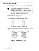
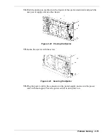
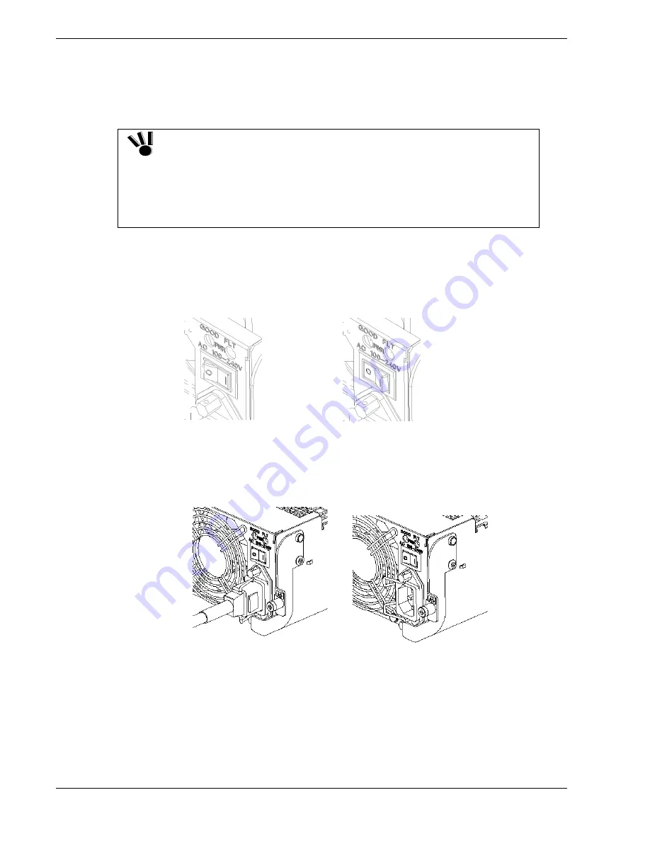
Press the power switch of the defective power supply to turn it off. 


ON OFF 

Figure 4-11    Turning the Power Supply Unit Off 

3. 

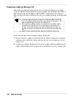
Unlatch the power cord stopper as shown below to release and unplug the power 
cord. 


Figure 4-12    Disconnecting the Power Cord 


4-10 Problem 

Solving


Содержание VERSA S1300 Series

Страница 1: ... U s e r s G u i d e NEC Storage S1300 ...

Страница 2: ......

Страница 3: ...etermined by the customer and is not warranted by NEC Computers International To allow for design and specification improvements the information in this document is subject to change at any time without notice Reproduction of this document or portions thereof without prior written approval of NEC Computers International is prohibited Trademarks HP UX is a registered trademark of Hewlett Packard Co...

Страница 4: ......

Страница 5: ...guration 1 15 Logical Disk Capacity 1 16 Arbitrary Logical Disk Capacity 1 16 Maximum Logical Disk Capacity 1 17 Dummy Logical Disk 1 18 Hot Spare Feature 1 18 Auto Repair Mode 1 19 Repair Time 1 19 Write Cache Feature 1 20 1 BBU Cache Enable Mode 1 21 1 CNT Cache Enable Mode 1 21 Cross Call Feature 1 22 Initial Assignment Feature 1 23 Auto Assignment Feature 1 23 Path Fail Over Feature 1 24 Expan...

Страница 6: ...the Disk Array Unit 2 20 Powering On the Disk Array Unit 2 21 Powering Off the Disk Array Unit 2 22 Upgrading the System 3 1 Overview 3 2 Adding Hard Disk Drives 3 2 Installation Procedure 3 3 Setting Procedures 3 6 Logical Disk Setting Procedure 3 6 Spare Disk Setting Procedure 3 6 Adding Disk Enclosures 3 7 Connecting a Disk Enclosure to the Disk Array Unit 3 7 Connecting a Disk Enclosure to Ano...

Страница 7: ... Specifications A 2 Creating a Logical Disk A 4 Unbinding the Existing Logical Disk A 4 Binding the New Logical Disk A 4 Turning On the Cross Call Feature A 5 How to Change the Topology and Data Transfer Rate A 6 Contents v ...

Страница 8: ...vi Contents ...

Страница 9: ...r storage system Chapter 2 Setting Up Your System tells you how to unpack the unit make cable connections and use your system It includes information on mounting the unit into a rack cabinet Chapter 3 Upgrading Your System provides you with instructions for expanding your system s storage capacity with additional hard disk drives and expansion disk enclosures Chapter 4 Problem Solving contains hel...

Страница 10: ...ons that could result in serious personal injury or loss of life CAUTION Cautions indicate situations that can damage the system hardware or software Ignoring the instructions contained in these boxes may result in equipment damage software damage or loss of data Note Notes give important information about the material being described viii Using This Guide ...

Страница 11: ...cts available for your disk array unit and tells you how to use the user s manuals included on the SAN STORAGE BUILDER CD ROM NEC Storage Manager User s Manual on the SAN STORAGE BUILDER CD Refer to this manual for detailed explanations on using the management software NEC Storage Manager that comes standard with your system NEC Storage Manager Messages Handbook on the SAN STORAGE BUILDER CD This ...

Страница 12: ...to disconnect power before opening your system can result in personal injury and or equipment damage Under no circumstances should you attempt to disassemble a power supply The power supply has no user replaceable parts Inside the power supply are hazardous voltages that can cause serious personal injury A defective power supply must be returned to your dealer Never connect the ground wire to a ga...

Страница 13: ...national agency approval marking The cord must be suitable for use in the end user country Consult your dealer or the local electrical authorities if you are unsure of the type of power cord to use in your country The voltage change occurs via a switch in the power supply Safety Notices for Users Outside of the U S A and Canada PELV Protected Extra Low Voltage Integrity To ensure the extra low vol...

Страница 14: ...e there is also a risk of heat or fire Use only the supplied power cords If the power cord rating is exceeded there is a risk of fire Also observe the following prohibitions to prevent damage to cords Do not pull on the cord Do not pinch the cord Do not bend the cord Keep chemicals away from the cord Do not twist the cord Do not place any object on the cord Do not bundle several cords Do not alter...

Страница 15: ... disconnecting any interface cable to from the system If the system is powered off but its power cords are plugged to a power source touching an internal device cable or connector may cause an electric shock or a fire Unless described herein never attempt to disassemble repair or alter the equipment There is a risk of electric shock or fire as well as malfunction You may want to unplug the equipme...

Страница 16: ...nt Temperature If installed in a closed or multi unit rack assembly the operating ambient temperature of the rack environment may be greater than the room ambient environment Therefore consideration should be given to installing the equipment in an environment compatible with a maximum rated ambient temperature of 35 C Reduced Air Flow Installation of the equipment in a rack should be such that th...

Страница 17: ...o room temperature before using it Keep the system away from magnetic forces Keep the system dry Do not wash the system with a wet cloth or pour fluid into it Protect the system from being bumped or dropped Check the system for condensation If condensation exists allow it to evaporate before powering on the system Keep the system away from dust sand and dirt Using This Guide xv ...

Страница 18: ...xvi Using This Guide ...

Страница 19: ...1 System Overview Overview System Chassis System Features ...

Страница 20: ...a reliability Expandable storage capacity with the connection of up to six disk enclosures accommodating up to 90 additional hard disk drives Centralized management using NEC Storage Manager software iSM which simplifies storage subsystem set up and management by integrating RAID configuration and volume management features into a single application NEC iSM software displays the configuration of l...

Страница 21: ...nstalled The front bezel is a cover protecting the hard disk drives and front chassis indicators To remove the front bezel release the lock with the accessory key grasp each side of the bezel with both hands and pull it out toward you A B Figure 1 2 Front View with front bezel Figure 1 3 shows the disk array unit with the front bezel removed E D B F C A Figure 1 3 Front View with front bezel remov...

Страница 22: ...first 3 slots from the left as viewed from the front and they are bound through RAID 5 Empty trays are installed in the remaining slots D Hard Disk Ready LED green The Hard Disk Ready LED lights green while the disk drive operates normally The LED blinks when the disk drive transfers data during the self test or initialization immediately after power on E Hard Disk Fault LED orange The Hard Disk F...

Страница 23: ...erly When the power switch is set to ON the four cooling fans are rotating Always check that the vents are not blocked D LAN card The LAN card is used to write the cache data remaining in the disk array unit into the disk drive before turning off the unit The LAN card is provided for changing the disk array configuration or monitoring failure of the disk array unit by using management software NEC...

Страница 24: ...ith a total of 4 fans Even if a fan fails proper cooling of the entire disk array unit is ensured However to guarantee the safe operation of the disk array unit replace the power supply immediately if a fan failure occurs When replacing a failed fan only two fans remain operative Therefore perform the replacing work within three minutes If the power supplies are removed for longer than five minute...

Страница 25: ...the power of the disk array unit The disk array unit has a redundant power configuration to prevent the entire unit from being shut down by a single power supply failure To take full advantage of this configuration turn on off both power switches C Power Fault LED orange The Power Fault LED lights if a fault occurs in the power supply or battery backup unit including a fan failure The LED stays of...

Страница 26: ...ithin about 3 minutes Disk drives power supplies and controllers generate heat within the disk array unit The fans in the power supplies ensure proper cooling of all of these components Therefore do not leave the disk array unit with one of the power supplies removed Doing so causes the disk drive temperature to rise which may significantly decrease the system reliability If the power supply is re...

Страница 27: ...p This LED is off during the self test or initialization immediately after power on G Linkup LED HOST LINK green The Linkup LED lights green if the respective FC connector FC port becomes operable to link up This LED is off during the self test or initialization immediately after power on H Host 2G LED green The Host 2G LED lights green while the FC interface with host is operating at 2Gbps I Link...

Страница 28: ...er Loosen the screw before using the ejector P DE DIAG LED green The DE DIAG LED lights green when the disk enclosure becomes ready for diagnosis Q DE DIAG connector The DE DIAG connector is provided to connect a cable for diagnosing the disk enclosure See Adding Disk Enclosures in Chapter 3 for more information on cable connection CAUTION When inserting a controller into the disk array unit push ...

Страница 29: ...isk array unit includes two redundant battery backup units for maximum availability A Figure 1 7 Battery Backup Unit A Connector This connector is used to connect the battery backup unit with the power supply System Overview 1 11 ...

Страница 30: ...Chapter 2 D Fault LED FLT LED orange The Fault LED lights orange if a fault occurs in the LAN card In normal operation the LED is off The Fault LED flashes when an error occurs while writing the data remaining in the cache memory to the disk drive with the Shut Down switch being ON For more information see Powering Off the Disk Array Unit in Chapter 2 E Shut Down LED SDN LED green The Shut Down LE...

Страница 31: ...system to a UPS If you want to change the current system connection contact your service representative If you change the connection by yourself the UPS will start at power failure but may fail to function normally Consequently operation may stop or data may be lost Disk Array Unit OUTPUT 1 OUTPUT 2 AC POWER Straight cable AC POWER OUTPUT 1 OUTPUT 2 To power board To power board Figure 1 9 Example...

Страница 32: ...which automatically starts data recovery after the replacement of the defected disk drive If a single disk drive is specified as the spare disk the data in the defected disk drive can be immediately recovered in the spare disk The use of this hot spare feature as well as the auto repair feature allows the data in the defected drive to be automatically recovered in the spare disk as soon as a disk ...

Страница 33: ...ing characteristics Table 1 2 RAID Levels Level Function Advantage Disadvantage RAID0 Striping Highest data read write rate Maximum storage capacity Data recovery disabled Fault in a single disk drive causes data to be lost RAID1 Mirroring Data recovery enabled Low speed data writing All data is written to two disk drives Minimum data recovery time Higher cost since twice the number of drives is r...

Страница 34: ...ta disks excluding parity disk The final value must satisfy the following two conditions It is a multiple of the striping unit It is a multiple of 1024 For example if your system consists of 7 disks configured with RAID5 6 data disks 1 parity disk the striping unit will be equal to the following value assuming that data is written in blocks of 256KB 256KB x 6 1536KB The logical disk capacity can o...

Страница 35: ... 511305 1024260 2044876 RAID1 1 1 2 34087 68284 136325 RAID5 2 P 3 68174 136568 272650 RAID5 3 P 4 102261 204852 408975 RAID5 4 P 5 136348 273137 545300 RAID5 5 P 6 170435 341420 681625 RAID5 6 P 7 204522 409704 817950 RAID5 7 P 8 238609 477988 954275 RAID5 8 P 9 272697 546274 1090600 RAID5 9 P 10 306783 614556 1226926 RAID5 10 P 11 340870 682840 1363251 RAID5 11 P 12 374957 751124 1499576 RAID5 1...

Страница 36: ...e disk array unit If a disk drive in the same FC loop as the spare disk fails the data in the defective disk drive can be regenerated to the spare disk After the data recovery the disk array unit operates normally if another disk drive is defected Since the unit also supports the hot swapping function the failed disk can be replaced while the power is on except for RAID level 0 To use the hot spar...

Страница 37: ...er management software The auto repair is enabled at the factory Note Even when the auto repair mode is disabled during a repair operation the current repair is not interrupted The new setting will be active from the next repair Also even when the auto repair mode is enabled in the repair waiting state the repair is not initiated The new setting will be active from the next repair as well When the...

Страница 38: ...interruptible power supply In general if the power is shut down before the data saved in the cache memory is written to disks the data in the cache memory will be lost To prevent this the battery backup unit retains data in the cache memory The backup time is restricted as follows Three days 72 hours in full charge status of both batteries The following conditions must be satisfied to make the wri...

Страница 39: ...tory set Note The single BBU condition refers to the state in which only one battery backup unit is mounted to the disk array unit or only one of the two battery backup units is available due to a failure 1 CNT Cache Enable Mode When only a single controller is installed the write cache operation mode can be set using the management software NEC Storage Manager However it is recommended to disable...

Страница 40: ...ogical disk numbers LDNs are accessible from both controllers By using the cross call feature LDNs can be accessed from the alternative path even when a controller fails so that the failure does not affect the operation Note To use the alternative path switching feature of the host the cross call feature must be turned on Figure 1 11 Cross Call Feature Note Please note that in the management softw...

Страница 41: ...ed The auto assignment feature allows you to access any logical disk in the subsystem from the unassigned controller if the assigned controller gets down When an I O is received on a logical disk not assigned to the local controller the system examines whether the adjacent controller is in down state If the adjacent controller is in down state the system reassigns the logical disk to the local con...

Страница 42: ...f such an event occurs the default setting cannot be restored with NEC Storage Manager management software depending on the system configuration resulting in system fault Dynamic Capacity Expansion The addition of a single disk drive to the rank configured with RAID 5 allows the rank logical disk capacity to be expanded Configurations that can be expanded range from 2 P to 13 P Physical hard disk ...

Страница 43: ...ded Windows 2000 If the LD is used as a basic disk and expanded the host system must be rebooted to recognize the logical capacity expanded If the LD is used as a dynamic disk and expanded the Rescan Disk command must be executed or the host system must be rebooted to recognize the logical capacity expanded System Overview 1 25 ...

Страница 44: ...using the access control feature For more information on using NEC Storage AccessControl refer to the Quick Reference Guide Before the access control feature can be used on this system the license key provided with the software must be entered from the management software in order to release the license lock You can release the license lock and make settings by yourself or contact your local servi...

Страница 45: ...sible number Registers the HD number in the access limitation list as inaccessible number Once the above setup is made The business server A can access logical disks LD00 LD01 LD04 and LD06 The business server B can access logical disks LD02 LD03 LD05 and LD07 LD08 and LD09 are accessible from neither business server These disks are accessible from business server B These disks are accessible from...

Страница 46: ...he HBA WWN and HD number in the access limitation list as inaccessible item Registers the WWN of HBA0 HBA1 and the HD number in the access limitation list as accessible item If the business server A supports the path switching feature the logical disks are accessible through switch 1 even in case that switch 0 is faulty and the access is rejected Once the above setup is made The server A can acces...

Страница 47: ...s provided with the software Please give the license code provided with the product to the designated maintenance person who is responsible for releasing the license lock Note Be sure to release the license lock A disk array unit without the license lock being released cannot receive any maintenance services because the operation cannot be guaranteed NEC Storage AccessControl for S1300 This softwa...

Страница 48: ...e storage control software by yourself However if you fail to update it the disk array unit may no longer operate Your local service representative provides the service additionally charged for updating the storage control software It is strongly recommended that you should ask your service representative to perform the update 1 30 System Overview ...

Страница 49: ...2 Setting Up the System Overview Unpacking the System Installation and Connection Procedures Using the Disk Array Unit ...

Страница 50: ...d its bottom face Also hold the front or side of the unit if possible and avoid grasping the power supply on the rear panel or the protrusions on the controllers When lifting the unit from the floor hold both projections on the controllers lift the rear side of the unit and then hold the bottom face When putting the unit on the floor put the front side first hold both projections on the controller...

Страница 51: ...ay Unit At least 3 hard disk drives and up to 12 fully functional carriers are installed see Figure 2 2 1 2 Power Cords US UK and European power cords are provided 6 2x3 3 Null Modem Cable DB9 DB9 1 4 Front Bezel 1 5 Key Allows you to open the front bezel 1 6 SAN STORAGE BUILDER CD ROM Documentation and Drivers CD Documentation includes this User s Guide and the manuals of the software programs av...

Страница 52: ...ed in the next section to mount the unit into a rack cabinet Connect the host bus adapter Connect the host bus adapter according to the manual provided with the host system or host bus adapter Then install the proper driver Connect the FC cable Use a cable that is compatible with the disk array unit Insert the connector until the latch emits a click Do not bend the cable forcibly Connect the power...

Страница 53: ...and unplugged All voltage is removed only when the power cords are unplugged Avoid excessive vibration and shock Dropping an electronic component can cause serious damage Installing the Rail Assemblies to the Rack Cabinet The following subsection describes how to install your rack mount disk array unit into a standard EIA 19 inch rack cabinet Before you begin select an appropriate location in your...

Страница 54: ...A B Figure 2 3 Installing the Rack Mounting Kit 2 6 Setting Up the System ...

Страница 55: ...claw at the top of the rail support on the square hole of the vertical mounting rail as shown in the figure below The notches on the right rail support must face left Rail support L Top claw Hook Figure 2 4 Installing the Rail Support 2 While holding the rail support engage the holes on the front of the rail assembly into the hooks Cutout Figure 2 5 Positioning the Front of the Rail Assembly Setti...

Страница 56: ...rack and slightly loosen the four countersunk head screws securing the inner and outer rails together see Figure 2 7 These screws must not be removed 5 Pull the inner rail toward you and engage the upper and lower tabs into the square holes on the rear vertical mounting rail Secure the inner rail using two M5 bolts Inner rail M5 bolt Countersunk head screw Figure 2 7 Securing the Rear of the Rail ...

Страница 57: ...e rail assembly is adjusted to the rack cabinet depth firmly tighten the countersunk head screws loosened in step 4 Countersunk head screw Figure 2 8 Tightening the Countersunk Head Screws Setting Up the System 2 9 ...

Страница 58: ...the disk array unit and position the rear of the unit onto the rails Then push it into the rack cabinet WARNING The system can weigh up to 45 kg To avoid personal injury make sure you have at least three people help you lift or move the system 2 Insert two M5 bolts on each handle of the disk array unit to secure it to the rack M5 bolt Figure 2 9 Securing the Disk Array Unit to the Rack 2 10 Settin...

Страница 59: ... rear of the rack cabinet connect the cables following the procedures described in the next section 2 Bundle all the cables together and tie wrap them to the cutout of the rail Attach the AC power cord as shown in the figure below AC cable Tie wrap Figure 2 10 Bundling and Tie Wrapping Cables Setting Up the System 2 11 ...

Страница 60: ... proper destinations based on the cable specification Do not push any cable connector excessively Each connector can be connected properly only when it is inserted to the mating connector in the correct direction and at the correct angle Proper insertion allows the connector to be inserted to the mating connector smoothly without excess force If the connector cannot be inserted smoothly do not ins...

Страница 61: ...e manufacturer Cable length limit FC optical cable for operating the host interface at 1Gbps Up to 500 m FC optical cable for operating the host interface at 2Gbps Up to 300 m Topology and data transfer rate settings Factory set topology and data transfer rate are as follows Topology FC AL Data transfer rate 2Gbps The topology and data transfer rate must be set correctly in accordance with the hos...

Страница 62: ...cy if the disk array unit is equipped with two controllers LC LC cables are necessary to connect the disk array unit to the host bus adapters DE diagnosis cable HSSDC HSSDC cable FC cable LC LC cable Figure 2 11 Connecting the Disk Array Unit to the Host System Note The additional disk enclosure is optional For more information see Adding Disk Enclosures in Chapter 3 2 14 Setting Up the System ...

Страница 63: ...ystem 1 Check the power supply Check that the power switches on the disk array unit and those on the host system are set to OFF A and that the plugs of the power cords are removed from AC outlets B ON OFF A B Figure 2 12 Checking the Power Supply Setting Up the System 2 15 ...

Страница 64: ...Array Unit Host system Host Bus Adapter HOST FC FC cable LC LC cable Similarly connect the other controller if your system is equipped with two controllers to the other host bus adapter installed in the host system 3 Set the AL PA Arbitrated Loop Physical Address Set the AL PA by using the AL PA switch on each controller The AL PA switch is factory set as follows CONT0 00 EF CONT1 01 E8 Set the AL...

Страница 65: ...D5 0A A6 29 67 48 31 67 D4 0B A5 2A 66 49 2E 68 D3 0C A3 2B 65 4A 2D 69 D2 0D 9F 2C 63 4B 2C 6A D1 0E 9E 2D 5C 4C 2B 6B CE 0F 9D 2E 5A 4D 2A 6C CD 10 9B 2F 59 4E 29 6D CC 11 98 30 56 4F 27 6E CB 12 97 31 55 50 26 6F CA 13 90 32 54 51 25 70 C9 14 8F 33 53 52 23 71 C7 15 88 34 52 53 1F 72 C6 16 84 35 51 54 1E 73 C5 17 82 36 4E 55 1D 74 C3 18 81 37 4D 56 1B 75 BC 19 80 38 4C 57 18 76 BA 1A 7C 39 4B 5...

Страница 66: ...low 1 Connect the separately sold Ethernet cable to the Ethernet connector modular jack on the LAN card 2 Connect the host system on which the management software NEC Storage Manager is installed to the Ethernet network Note Simply connecting the cable to the LAN card does not make it possible to use NEC Storage Manager through Ethernet Further steps are necessary Contact your service representati...

Страница 67: ...low to connect the power cords 1 Check the power supply Check that the power switches on the disk array unit and those on the host system are all set to OFF ON OFF Figure 2 13 Turning Off the Unit 2 Connect the power cords to the power receptacles Insert the connector of the power cord into the power plug on the power supply and secure the power cord using the stopper Figure 2 14 Connecting Power ...

Страница 68: ...st system or the initialization is being operated do not turn on off the power of the disk array unit or host system Do not reset the host systems Always protect the disk array unit from vibrations and shocks especially when the Access LED green of the controller lights or blinks and a disk access operation is indicated on the host system It is recommended that important files be backed up to magn...

Страница 69: ...y unit and additional disk enclosure at the rear of the unit 3 When turning on the power confirm that the Power Good LEDs green on all the power supplies and Power LEDs green on the front panel of the disk array unit and additional disk enclosure go on Power supply starts The disk array unit performs the self test and initialization immediately after the power is turned on When the self test and i...

Страница 70: ...C press both power switches at the rear of the disk array unit and then press both power switches at the rear of the additional disk enclosure to turn power off The disk array unit has a redundant power configuration to prevent the entire unit from shutting down due to a single power supply failure Therefore turn off all the power switches at the rear of the additional disk enclosure and the disk ...

Страница 71: ... unit restarts the disk array unit normally accepts I O operations by the host system 3 Confirm that the SDN LED of the LAN card installed in the disk array unit stops flashing and goes on and then turn off the AC power according to the procedure described on previous page 4 The SDN LED flashes while data remaining in cache memory is being written onto the disk drive Do not turn off the AC power w...

Страница 72: ... the host writes the cache data on the host into the disk array unit Confirm that the cache data on the host is successfully written into the disk array unit and no data remains in cache on the host and on the disk array unit before turning off the AC power You can check the remaining data using the Hard Disk Ready LED If the Hard Disk Ready LED flashes some data remains in the cache memory of the...

Страница 73: ...3 Upgrading the System Overview Adding Hard Disk Drives Adding Disk Enclosures ...

Страница 74: ...our disk array unit is equipped with 15 hot swap hard disk drive bays providing an expandable storage capacity The unit comes with a minimum of three hard disk drives installed in dedicated trays Empty slots contain fully functional trays for installation of additional hard disk drives This section provides instructions for installing additional hard disk drives Figure 3 1 Hard Disk Drive 3 2 Upgr...

Страница 75: ... or more trays at a time Follow the procedure below to install a hard disk drive 1 Put the location label on the additional hard disk drive Before installing the hard disk drive select the location label corresponding to the location where the disk drive is to be installed and put it on the additional hard disk drive Location label Figure 3 2 Location Label Note Additional hard disk drives must be...

Страница 76: ...ock is released B Then hold the handle and remove the empty tray C A B C Figure 3 3 Removing the Empty Tray Be sure to keep removed empty trays in the designated place For proper cooling and airflow always install a tray in empty slots Heat generation increases the failure rate and may even cause data loss 3 4 Upgrading the System ...

Страница 77: ...sk drive to the end Figure 3 4 Installing the Additional Hard Disk Drive After the disk drive is inserted to the end securely push the ejector down until it clicks into locked position Figure 3 5 Locking the Additional Hard Disk Drive When inserting the hard disk drive into the disk array unit push it as far as it will go and then lock the ejector Incorrect insertion may cause malfunction Upgradin...

Страница 78: ...re to make backup copies of necessary data before performing the addition procedure Spare Disk Setting Procedure Only RAID levels 1 5 and 10 support the spare disk feature Set the spare disk by using NEC Storage Manager or contact your service representative for setting of the spare disk The spare disk drive must be installed in slot 14 If slot 14 already contains a spare disk drive install the se...

Страница 79: ...Connect the additional disk enclosure to the disk array unit using the FC cables HSSDC provided with the enclosure or the FC cables HSSDC included in the separately sold DE expansion cable kit Push the connector at either end of the cable into the DE FC connector for connection with a disk enclosure located on controller 0 CONT0 of the disk array unit until a click is heard The FC cable has the sa...

Страница 80: ...isk array unit is equipped with 2 FC controllers connect the DE DIAG connector on controller 1 CONT1 of the disk array unit to the DE DIAG connector PORT0 on adapter 1 ADP1 of the additional disk enclosure 4 Set the AL PA switch located on the additional disk enclosure The AL PA switches on both adapters of the additional disk enclosure are factory set to 1 Make sure that both AL PA switches are s...

Страница 81: ...l disk enclosure by setting the power switches of the enclosure to ON Be sure to install disk drives into PD0 and PD1 slots of the additional disk enclosure If the disk drives in both PD0 and PD13 slots are faulty or they have not been installed the Service LED on the additional disk enclosure and the Fault LED on the ADP0 side light If the disk drives in both PD1 and PD14 slots are faulty or they...

Страница 82: ... be connected to the adapter of DE1 Push the connector at the other end of the FC cable into the FC IN connector on adapter 0 ADP0 of DE2 until a click is heard Similarly connect the FC OUT connector on adapter 1 ADP1 of DE1 to the FC IN connector on adapter 1 ADP1 of DE2 3 Connect the additional disk enclosure to DE1 using the DE diagnosis cables provided with the new enclosure or the DE diagnosi...

Страница 83: ... additional disk enclosure are factory set to 1 As each disk enclosure must be identified by a unique ID in the arbitrated loop set AL PA switches on both adapters of the newly installed enclosure to a value ranging between 2 and 6 that is not used by another device For example set the AL PA of the second disk enclosure connected to your disk array unit to 2 Note Both adapters on the disk enclosur...

Страница 84: ...wo power switches on the additional disk enclosure are set to OFF ON OFF Figure 3 13 Turning the Power Supply Off 7 Insert the power cords provided with the additional disk enclosure into the plugs on the power supply units and secure them with the power cord stoppers Figure 3 14 Connecting the Power Cord to the Power Receptacle 8 Insert the plugs of the power cords provided with the additional di...

Страница 85: ...r they have not been installed the Service LED on the additional disk enclosure and the Fault LED on the ADP1 side light The newly installed disk enclosure must then be configured properly using NEC Storage Manager For more information contact your service representative Removing a Disk Enclosure You should follow the steps below to remove a disk enclosure 1 Unbind all RANKs LDs in the disk enclos...

Страница 86: ...3 14 Upgrading the System ...

Страница 87: ...4 Problem Solving Overview Troubleshooting Checklists Fault LED Indicator Description Replacing Defective Devices Computer Viruses Service and Support Disposing of the Disk Array Unit ...

Страница 88: ...tlets Then ask your sales agent or maintenance engineer to inspect and repair the disk array unit immediately Using the disk array unit as it is may cause electric shock or fire Never attempt to repair the disk array unit by yourself Only a technically qualified person should repair it because it contains hazardous voltages that can cause personal injury CAUTION If a fault occurs in the disk array...

Страница 89: ...hapter 2 for more information Is the setting of the host bus adapter or FC AL switch correct Provide the proper setting referring to the user s guides of the host bus adapter FC AL switch host system and added peripherals Is the used host bus adapter compatible with the disk array unit Contact your sales agent for a list of approved HBAs The host system cannot recognize the disk array unit Is the ...

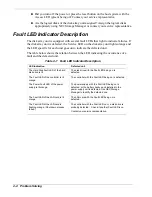
Страница 90: ...nd the defected unit Table 4 1 Fault LED Indicator Description LED indication Defected unit The Hard Disk Fault LED of the hard disk drive is lit The disk drive with the Fault LED being on is defected The Fault LED of the controller is lit orange The controller with the Fault LED being on is defected The Power Fault LED of the power supply is lit orange The power supply with the Fault LED being on...

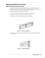
Страница 91: ...out powering off the disk array unit Follow the procedure below to replace a controller 1 Identify the defected controller by locating the Fault LED being lit 2 Remove all the cables connected to the defected controller 3 Loosen the screw securing the ejector of the target controller Figure 4 1 Releasing the Ejector 4 Put your finger on the protrusion as shown in the figure of the ejector and pull...

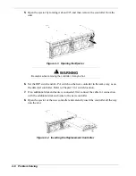
Страница 92: ... on the new controller in the same way as on the defected controller Refer to Chapter 1 for switch location 7 If an additional disk enclosure is connected first connect the cable for connection with the additional disk enclosure to the new controller 8 Open the ejector of the new controller and carefully insert the controller all the way into the slot Figure 4 4 Inserting the Replacement Controlle...

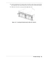
Страница 93: ...sh the ejector the part indicated by the arrow in the figure until the controller is inserted firmly Figure 4 6 Pushing the Ejector of the Replacement Controller 11 Secure the ejector with the screw Figure 4 7 Securing the Ejector of the Replacement Controller 12 Connect the FC cables removed in step 2 as they were before Problem Solving 4 7 ...

Страница 94: ...he LAN card 1 Loosen the screw securing the LAN card Figure 4 8 Releasing the Screw Securing the LAN Card 2 Grasp the protrusions shown in the figure below and pull the defected LAN card toward you Do not remove cables Remove the LAN card with the cables being connected Figure 4 9 Removing the LAN Card from the Unit 3 Remove all the cables from the defected LAN card and connect them to the replace...

Страница 95: ...the cables being connected Push the protrusions at the top and bottom of the LAN card so as to insert the card firmly 5 When the LAN card is securely inserted tighten the screw Figure 4 10 Securing the Replacement LAN Card to the Unit Problem Solving 4 9 ...

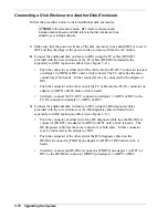
Страница 96: ...he new power supply before removing the old one and then replace it within about 5 minutes If the power supply is removed for longer than 5 minutes the shutdown sequence is executed by the security feature of the disk array unit Read the entire procedure before replacing the power supply Follow the procedure below to replace a power supply 1 Identify the defective power supply whose Power Fault LE...

Страница 97: ... the Ejector 5 Put your finger on the protrusion as shown in the figure of the ejector and lift it up Figure 4 14 Pulling the Ejector 6 When the ejector is rotated about 90o remove the defective power supply unit Figure 4 15 Removing the Defective Power Supply Unit Problem Solving 4 11 ...

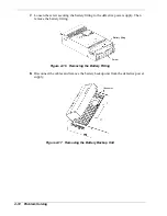
Страница 98: ...r supply Then remove the battery fitting Battery fitting Screw Figure 4 16 Removing the Battery Fitting 8 Disconnect the cables and remove the battery backup unit from the defective power supply Connector Figure 4 17 Removing the Battery Backup Unit 4 12 Problem Solving ...

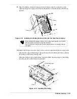
Страница 99: ... battery connector being fully inserted Incorrect insertion may cause a power supply failure or a battery backup unit failure 10 Install the fitting removed in step 7 above onto the replacement power supply unit Insert the two tips of the fitting to the positions shown in the figure below and put the fitting on the battery backup unit When the fitting is put on the battery insert the BBU inserting...

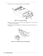
Страница 100: ... the Fitting 12 Make sure that the power switch of the new power supply unit is set to OFF and that the power cord is unplugged 13 Insert the new power supply into the slot with the ejector opened and push it to the innermost Figure 4 21 Inserting the New Power Supply Unit 4 14 Problem Solving ...

Страница 101: ...supply unit into the chassis Figure 4 22 Closing the Ejector 15 Secure the ejector with the screw Figure 4 23 Securing the Ejector 16 Plug the power cord in the connector on the power supply and secure the power cord with the stopper Press the power switch to turn power on Problem Solving 4 15 ...

Страница 102: ...replacing a battery backup unit prepare the new battery backup unit before removing the old one and then replace it within about 5 minutes If the power supply is removed for longer than 5 minutes the shutdown sequence is executed by the security feature of the disk array unit Read the entire procedure before replacing the battery backup unit Follow the procedure below to replace a battery backup u...

Страница 103: ...sk drive having the same storage capacity and same rotational speed When installing more than one disk drive or moving disk drives to other slots remove trays one by one Do not remove two or more trays at a time Changing the location of disk drives with LDNs assigned may result in data loss Follow the procedure below to replace a hard disk drive 1 Identify the defective hard disk drive whose Hard ...

Страница 104: ...ive and then put the label on the replacement disk drive Location label Figure 4 25 Location Label 4 With the ejector of the replacement disk drive opened engage the upper and lower guides of the drive with the grooves on the slot and slowly insert the disk drive completely Figure 4 26 Inserting the Hard Disk Drive in the Bay 4 18 Problem Solving ...

Страница 105: ...ws the data recovery to be started automatically If the auto repair feature is set to OFF issue a recovery instruction from the management software in manual mode to start recovery Otherwise the degraded state reduce shown as the logical disk status remains Setting the auto repair feature to ON in recovery wait state does not start recovery The setting is enabled starting with the next recovery 7 ...

Страница 106: ...you have any question on the occurrence of a fault or error on the unit do the following preparations before calling your technical support center Write down the failure or fault status and questions Write down the configuration of the peripherals connected to the host system and the software products used in the disk array unit Keep this manual the manuals on the peripherals connected to the host...

Страница 107: ...A Appendix Technical Specifications Creating a Logical Disk How to Change the Topology and Data Transfer Rate ...

Страница 108: ...able vibration level 0 25G Storage Temperature 10 C to 60 C Relative humidity 10 to 80 Web bulb temperature 8 C to 29 C Allowable vibration level 0 5 G Host interface Type FC AL optical Data transfer rate max 2 Gb s 1 Gb s Number of host interfaces 1 per controller 2 per unit Maximum cable length 300 m optical Disk interface Type FC AL copper Data transfer rate max 2 Gb s 1 Gb s Number of disk int...

Страница 109: ...e 8 hours from empty to full charge Backup mode Cache memory backup 3 days for 2 controllers and 2 BBUs with 512MB per controller Redundant configuration 1 1 Hot swap Yes Life expectancy 2 5 years Fan Type DC fan Redundant configuration 3 1 Hot swap Yes Life expectancy 50 000 hours Power supply Input voltage 100 to 240 VAC 10 2 50 60 Hz Maximum power consumption 550 VA Additional disk enclosure 52...

Страница 110: ...oftware For instance follow the procedure below to unbind logical disk 0 that is already bound Unbinding of LD Select 5 LD Unbind from the management software NEC Storage Manager menu and specify LUN 0 Unbinding of RANK Select 2 RANK Unbind from the management software NEC Storage Manager menu and specify PDG 0 and RANK 0 Binding the New Logical Disk To create the logical disk first bind the RANK ...

Страница 111: ...r Type s PDG No 0 RANK No 0 LD Capacity 204520 Number of LD 1 Format Time 0 Turning On the Cross Call Feature To enable both controllers to access all logical disks it is necessary to turn on the cross call feature However data corruption may occur if the transmission path feature is not provided by an additional software component such as NEC Storage PathManager If so it is recommended to use the...

Страница 112: ...ide the bits using the tip of a ballpoint pen Slide bit 3 to change the topology Slide bit B to change the data transfer rate Refer to Table A 2 on the next page for more information on the function of each switch Rear of the controller Figure A 1 Location of the Dip Switches on the Controller Board The topology and data transfer rate should be changed appropriately depending on connected devices ...

Страница 113: ...d 3 OFF at shipment Topology OFF FC_AL ON Fabric A9E2 4 OFF Reserved 5 OFF Reserved 6 ON Reserved 7 OFF Reserved A9E1 8 OFF Reserved 9 OFF Reserved A OFF Reserved B ON at shipment Host Mode OFF 1Gbps ON 2Gbps A9D C ON Reserved Note Only bits 3 and B may be changed Do not change other bits Appendix A 7 ...

Страница 114: ...A 8 Appendix ...

Страница 115: ... 1 18 Dynamic capacity expansion 1 24 E Expand LUN 1 24 F Fault LED indications 4 4 Fibre Channel controller replacing 4 5 Front panel 1 3 H Hard disk drive adding 3 2 replacing 4 17 Hot spare 1 18 I Initial assignment feature 1 23 Installation flow 2 4 L LAN card 1 12 replacing 4 8 Logical disk creating A 4 Logical disk capacity 1 16 M Mounting the disk array unit into a rack cabinet 2 5 N NEC St...

Страница 116: ...0 System chassis 1 3 System features 1 14 System overview 1 2 System power 1 7 T Technical specifications A 2 Topology changing A 6 Troubleshooting checklists 4 3 U Unpacking the system 2 2 UPS connection 1 13 W Write cache feature 1 20 Index 2 ...

Страница 117: ...xx ...

Страница 118: ... ...

Отзывы: