3-28 Disassembly and Reassembly
6.
Insert the device the rest of the way into the device bay, making sure that the
locking tabs on the sides of the drive engage the brackets on each side of the
device bay.
7.
Secure the device to the bay with two screws (see the first figure in
“Removing a 5 1/4-Inch Device — Small Desktop or Desktop”).
8.
Replace the front panel.
For a small desktop system see “Replacing the Front Panel — Small
Desktop.”
For a desktop system, see “Replacing the Front Panel — Desktop.”
9.
Replace the system unit cover (see “Replacing the Small Desktop or
Desktop Cover”).
10.
Run the Setup program to set the new configuration (see “CMOS Setup
Utility” in Section 2).
Removing a 5 1/4-Inch Device — Minitower
Use the following procedure to remove a 5 1/4-inch device from a 5 1/4-inch
accessible device bay.
1.
Remove the left side cover (see “Removing the Minitower Side Covers”).
2.
Remove the front panel (see “Removing the Front Panel — Minitower”).
3.
Label and disconnect the device cables. If necessary, remove the top cover
for access to the connectors (see “Removing the Minitower Top Cover”).
4.
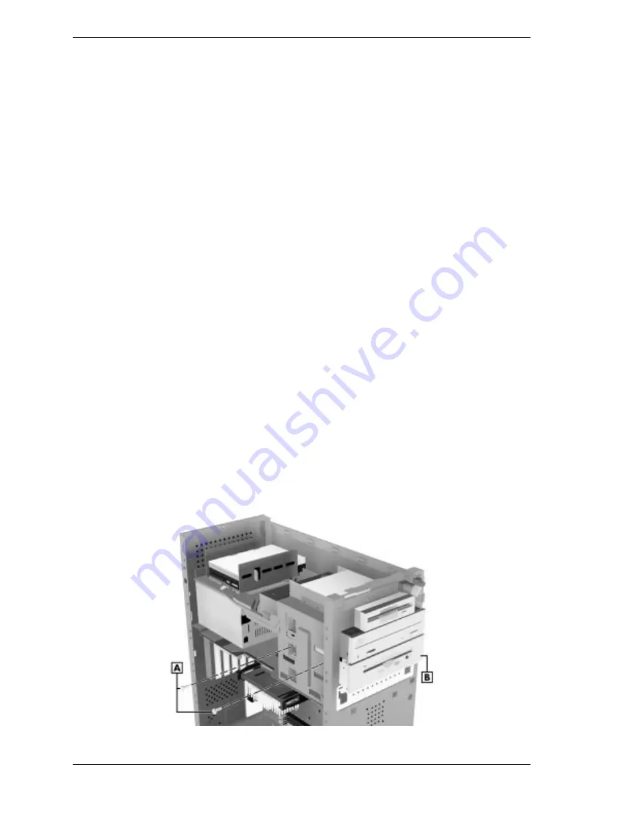
Remove the two screws on the left side of the device (see the following
figure).
Locating 5 1/4-Inch Device Screws — Minitower
A – Screws (2)
B – Device
Содержание POWERMATE ES 5200 - SERVICE
Страница 18: ...1 System Overview Configurations Features Components ...
Страница 168: ...4 System Board Connectors Jumpers and Sockets Components Resources ...
Страница 204: ...5 Riser Board Riser Board Connectors Small Desktop Riser Board Connectors Desktop Riser Board Connectors Minitower ...
Страница 222: ...7 Preventive Maintenance System Cleaning Keyboard Cleaning Mouse Cleaning ...
Страница 226: ...8 Troubleshooting Checklist Diagnostics ...
Страница 237: ...9 NEC CSD Information Services Service Telephone Numbers Technical Support Product Information ...
Страница 300: ...Regulatory Statements FCC Statement Note for Canada Battery Replacement Battery Disposal ...


