CHAPTER 4 OPERATION USING GUI SOFTWARE
User’s Manual U17454EJ1V0UM
48
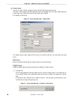
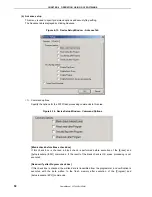
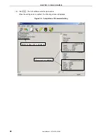
<3> Supply
oscillator
Select the clock that determines the programming, data transfer, and transfer rates, in this area.
Figure 4-10. Device Setup Window – Supply Oscillator
[Frequency box]
Sets the clock frequency of the target system.
Remark Check the selectable communication rate with the user’s manual of each device.
If communication is performed by using CLK of the FPL3, input 8 MHz when MODE2 is
set, or input 16 MHz when MODE3 is set.
[Multiply rate]
Sets the division rate or multiplication rate of the target device.
If the target device includes the PLL circuit, input the division rate or multiplication rate depending on
the environment used.
Since the division rate or multiplication rate varies depending on the device, set it by checking the
device specifications.
If the target device does not include the PLL circuit, select “1.0”.
The default setting is displayed by the parameter file in the initial screen.
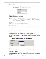
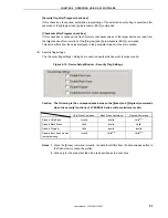
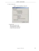
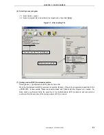
<4> Operation Mode
The flash memory may be divided into blocks or areas depending on the target device.
This menu is used to select the operation mode of the flash memory. Some devices do not have
either or both division modes Block and Area. In this case, a mode that is not available cannot be
selected.
Figure 4-11. Device Setup Window – Operation Mode Selection
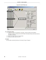
[When Chip is selected]
The entire flash memory area of the target device is subject to rewrite processing.
[When Block is selected]
Specify the Block number range subject to rewrite processing by using Start/End.
The Start/End list boxes display the Block number where the flash memory of the target device is
configured.
Содержание PG-FPL3
Страница 2: ...User s Manual U17454EJ1V0UM 2 MEMO ...

