CHAPTER 2 HARDWARE INSTALLATION
User’s Manual U17454EJ1V0UM
12
2.3 System
Configuration and Components
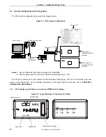
The FPL3 system configuration is as given in the diagram below.
Figure 2-1. FPL3 System Configuration
USB cable
(Mini-B type)
Note 1
Target system
compatible with FP4
connector
Host machine
Target cable
FPL3-FA
PG-FPL3
FA adapter
Note 2
IECUBE Accessory Disk
Target system not
compatible with FP4
connector
Notes 1. Use the USB cable (Mini-B type) included with the IECUBE.
2. The FA adapter board is a product of Naito Densei Machida Mfg. Co., Ltd.
The FPL3 is connected to the host machine via the USB cable (Mini-B type). The FPL3 is connected to the user
system via the target cable. For the detailed specifications of the target cable and connector, refer to CHAPTER 6
CONNECTORS AND CABLES.
2.3.1
FPL3 display specifications, connector, and MODE switch settings
Figure 2-2. Layout Drawing of Connectors and LEDs
CLK
16MHz
8MHz
5V
3.3V
3
Target
VDD Target
MODE
2
1
1 2 3
Status
Power
MODE
Target
MODE switch
Target cable connector
USB connector
Power LED
Status LED
Содержание PG-FPL3
Страница 2: ...User s Manual U17454EJ1V0UM 2 MEMO ...


