CHAPTER 2 HARDWARE INSTALLATION
User’s Manual U17454EJ1V0UM
16
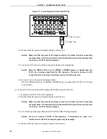
Figure 2-5. Connecting Target Cable with FPL3-FA
<2> Make sure that the power to the target system is not turned on.
Caution Make sure that the power to the target system is not turned on before connecting
the target cable. If the target cable is connected after the power to the target system
is turned on, the FPL3 may be damaged.
<3> Connect the FP4 connector with the connector installed in the target system.
Caution When the MODE switch is set to MODE2 or MODE3 (power is supplied from the
FPL3), V
DD
is always output from the FP4 connector. Be sure to remove the FP4
connector before inserting or removing a device in the target system.
<4> Be sure to turn on the power to the target system.
(When the MODE switch is set to MODE2 or MODE3, power is supplied from the FPL3, so this step
is not required.)
(b) When the FPL3 is connected with the target system without using the FPL3-FA
<1> Disconnect the FPL3-FA from the target cable.
<2> Make sure that the power to the target system is not turned on.
Caution Make sure that the power to the target system is not turned on before connecting
the target cable. If the target cable is connected after the power to the target system
is turned on, the FPL3 may be damaged.
<3> Connect the tip of the target cable marked “0.GND” to GND of the target system.
Caution Be sure to connect “0.GND” at the beginning. If connections are made in an
incorrect order, the FPL3 and target system may be damaged.
<4> Make sure that the power to the target system is not turned on.
Match the number.
Tip of target cable
0.
GND
Содержание PG-FPL3
Страница 2: ...User s Manual U17454EJ1V0UM 2 MEMO ...


