CHAPTER 2 HARDWARE INSTALLATION
User’s Manual U17454EJ1V0UM
15
2.3.6 Connection
procedure
The procedure for connecting the FPL3 is described below.
Caution Be sure to install the software (GUI software driver) before making connections.
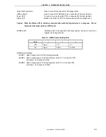
(1) Set the MODE switch according to the power supply of the target system.
Caution Be sure to set the MODE switch before making connections with the host machine and target
system. If connections are made based on an incorrect setting, the FPL3 and target system
may be damaged.
Figure 2-4. MODE Switch Setting
1 2 3
Status
Power
MODE
Target
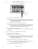
(2) Connect the host machine with the FPL3 via the USB cable. (Check that the Power LED is turned on in green.)
Cautions 1. Be sure to perform this step before making a connection with the target system. If
connections are made in an incorrect order, the FPL3 and target system may be damaged.
2. When the MODE switch is set to MODE2 or MODE3 (power is supplied from the FPL3), the
voltage set to the V
DD
pin is output when the FPL3 is connected with the host machine.
(3) Connect the target system with the FPL3 (follow either setting (a) or (b)).
(a) When FPL3 is connected with a target system that has a 16-pin connector usable with the FP4 connector
<1> Connect the tip of the target cable with the target connector of the FPL3-FA.
Connect the tip of the target cable with the target connector of the FPL3-FA so that the number
marked on the tip of the target cable matches to the number marked on the FPL3-FA board.
Remark The FPL3-FA is connected with the target cable at shipment.
Set the MODE switch.
1: Target/Target
2: 3.3 V/8 MHz
3: 5 V/16 MHz
Содержание PG-FPL3
Страница 2: ...User s Manual U17454EJ1V0UM 2 MEMO ...


