4.3.6.2.
Use of the integrated brake in the motor
WARNING
When defining the brake connections, take into account the possible voltage drop on the cables that carry the
power supply even to the logical sections of the DR2020.
WARNING
the brake supply is NOT obtained inside the drive. It is brought via the 24V auxiliary power supply; take into
account that it must provide for the brake feeds. When many DR2020 modules are installed, make sure to
place, if possible, the modules with the brake at the beginning of the system.
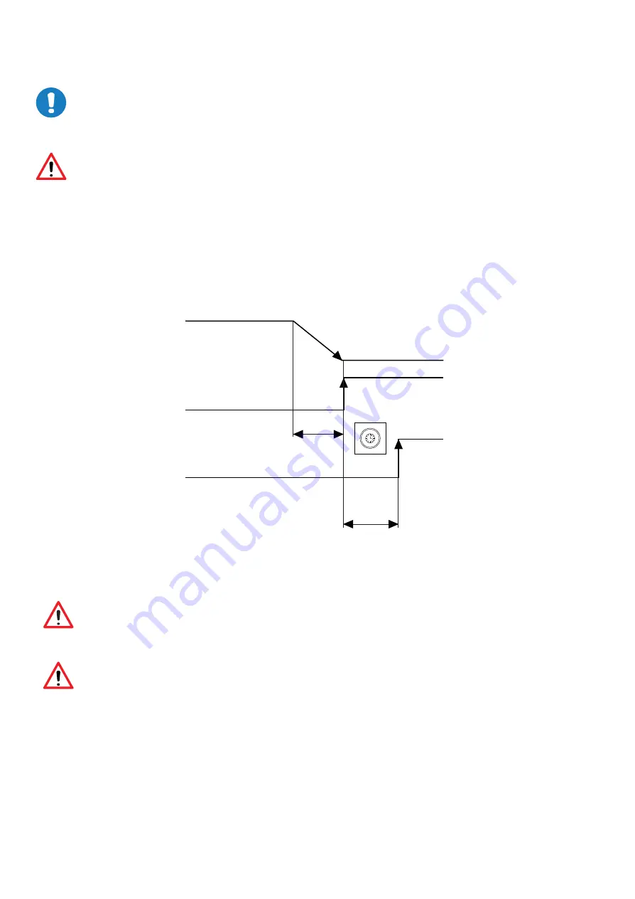
The figure shows the functional and time relations between enabling, activation signal and velocity command. Motor brake times
vary depending on the motor models, and reference shall be made to motor model data.
The external brake activation command must reach the drive when the motor speed is close to or equal to 0. The delay introduced by
the drive between receiving the command and its transmission to the brake is less than 125 us. The delay in brake activation
depends on the type of brake and is specified by the motor manufacturer.
Motor speed
Motor stopped
Command of voltage to the brake
Brake activation
A
B
Fig 4.11 Diagram of brake activation times
WARNING
The same information given for the motor cable applies, so particular care should be paid with shielding, even if the
conductors are not already incorporated in the motor cable.
WARNING
The use of the motor brake does not guarantee any personal safety. Vertical loads in particular require an additional
mechanical brake to operate safely; using safety boards, for example.
A.
Machine deceleration time (variable)
B.
Brake activation (300 ms)
MAR2-E-191
40


