ATTENTION
In order to be validated according to categories 1 to 4, on the basis of safety principles in UNI EN ISO 13849-2:2008, table
D.2, external cables that run into the X1 connector must have shields connected to the earthing circuit
Input/output electrical specifications
Input channel
I
nom
= 50mA (± 10%)
V
nom
= 24Vcc (± 10%)
V
max
= 30 Vcc
Output – Channel testing
I
max
= 200 mA
Vmax = 30 Vd
c
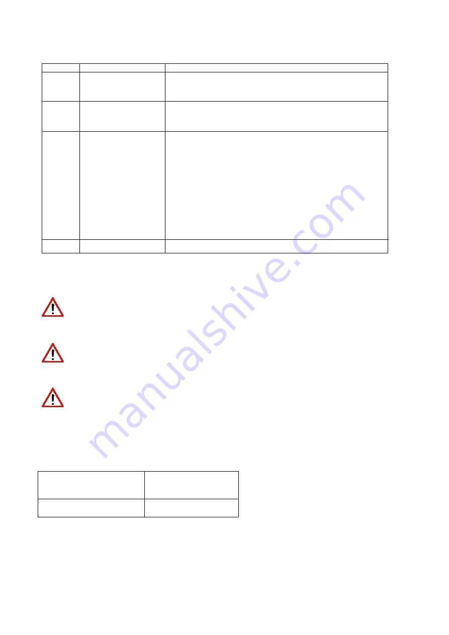
Name
Function
1
+ “Channel1”
Input +24Vdc of channel 1. This input must be high (+24Vdc) to
power the motor. When the input is low (0V) the motor is not
powered.
2
+ “Channel 2”
Input +24Vdc of channel 2. This input must be high (+24Vdc) to
power the motor. When the input is low (0V) the motor is not
powered.
A
- “Channel 1/2”
0V of Channel 1/2
The "hardware feedback" electrical contact consists of a
"Photo-Mos" relay protected by a fuse.
When both control channels "Channel 1" and "Channel 2" are at
low logic level (0V), the STO circuit is in safe mode (safety
function enabled), the monitoring signal is active and provides
closed contact.
In all remaining cases the monitoring signal is always off, and
provides open contact.
The monitoring channel of the complete system must include
this signal to execute the plausibility check correctly
3
Pin
Monitoring Channel
WARNING
To prevent short circuits between the input and the test signal, the multi-strand cables of the two channels must
terminate with a cable terminal or other appropriate device
WARNING
The test signal wiring of the two channels must be protected from short circuits to voltage sources; external voltage
must never be applied to the test signal, not even in the case of failure
DR2020
MAR2-E-191
86


