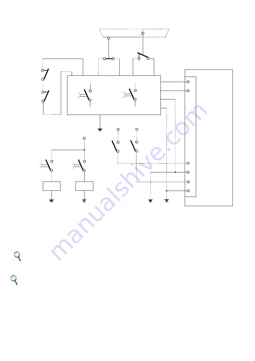
7.7. Application Example
33
34
37
38
A
1
- SW1
- SW1
CLOSED
OPEN
6
5
1
2
3
4
DRIVE
+ 24 V
+ 24 V
+ 24 V
37
38
33
34
- A1
- A1
SAFETY PLC
Ch 1 Verification
Ch 2 Verification
JRIC 1
Ch 1
Ch 2
- Q1
- Q1
- Q2
- Q2
- Q1
- Q2
Example of Safe Torque Off after a controlled stop
Description
Two redundant channels are used. The SW1 and SW2 repair switches are connected to the A1 safety PLC which controls the two
Q1 and Q2 contactors with linked contacts. The NO contacts of Q1 and Q2 control the two input safety channels of DR2020 to
turn off motor power connections. The NC contacts of Q1 and Q2 are used in series to control the A1 safety PLC in the case that
an NO contact is welded. The two output safety channels of the DM2020 are connected to the A1 safety PLC to provide
diagnostics coverage of the DR2020 subsystem.
INFORMATION
In the example, a controlled stop may be obtained by using the delayed outputs of A1. The controlled stop is not a safety
function incorporated in the drive, so the relative circuit is not shown in the figure.
According to UNI EN ISO 13849-1:2008, the subsystem relative to input and output devices can attain a PL of “e” because:
• the channels are redundant
• the SW1 and SW2 switches have a high MTTFd and DC
• the SW2 switch operates with positive opening
• the Q1 and Q2 contactors have a high MTTFd and DC
• the value of CCF is > 65
DR2020
MAR2-E-191
87


