User
Guide
for
Axoclamp
900A
10.
Connect
oscilloscope
channel
1
to
Headstage
1
SCALED
OUTPUT.
11.
Connect
oscilloscope
channel
2
to
rear
panel
SYNC
BNC.
12.
In
the
Headstage
2
meter
group,
click
Switch
to
TEVC
at
threshold
.
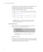
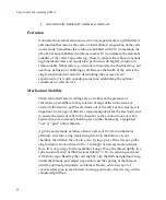
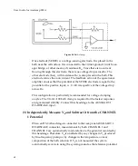
The
following
waveforms
should
result:
Figure
36.
Automated
Mode
Switching
signals.
IN0
is
10×
the
membrane
potential
in
Channel
1.
IN1
is
the
Mode
signal.
HIGH
is
V
‐
Clamp
mode
and
LOW
is
I
‐
Clamp
mode.
Explanation
of
the
waveform:
ο
The
membrane
potential
starts
at
zero
in
I
‐
Clamp
mode.
ο
Headstage
2
injects
a
1
nA
current
into
the
membrane.
ο
This
current
is
picked
up
in
Headstage
1
as
seen
at
the
50
ms
point
with
the
exponentially
rising
membrane
potential.
54


