User
Guide
for
Axoclamp
900A
Gain
The
clamp
gain
during
dSEVC
mode
is
given
in
nA/mV.
This
refers
to
how
many
nanoamperes
the
output
current
will
change
by
for
each
millivolt
of
difference
between
V
m
(the
membrane
potential)
and
V
cmd
(the
command
potential).
The
value
indicated
on
the
front
panel
is
the
average
value
(G).
The
average
value
depends
upon
the
instantaneous
gain
during
the
current
‐
passing
period
(G
T
)
and
upon
the
duty
‐
cycle.
Series
Resistance,
R
s
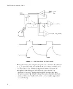
In
dSEVC
mode
the
effect
of
series
resistance,
R
s
,
is
to
slow
the
microelectrode
response.
Thus,
the
current
does
not
completely
decay
to
baseline
before
the
voltage
measurement.
Since
the
potential
recorded
by
the
membrane
potential
is
the
sum
of
the
voltage
across
R
s
and
the
membrane
resistance,
R
m
,
there
is
an
error
in
the
membrane
potential
recorded.
The
added
consequence
is
that
R
s
limits
the
maximum
rate
at
which
the
membrane
can
be
charged.
To
eliminate
R
s
altogether,
watch
the
MONITOR
output
and
make
sure
the
transient
decays
completely
before
the
next
sample
is
taken.
Advantages
of
a
Patch
Pipette
It
turns
out
that
a
patch
pipette
is
ideal
for
dSEVC.
That
is,
when
R
e
(microelectrode
resistance)
is
very
small,
its
time
constant
is
fast.
In
addition,
the
magnitude
of
the
voltage
transient
across
the
microelectrode
for
a
given
current
is
proportional
to
R
e
and
therefore
small
when
R
e
is
small.
This
double
advantage
of
low
R
e
values
means
that
the
dSEVC
can
be
cycled
very
rapidly
without
introducing
a
sampling
error.
Noise
in
DCC
and
dSEVC
Modes
The
noise
inherent
in
discontinuous
single
‐
electrode
clamps
(discontinuous
current
clamp
or
discontinuous
single
‐
electrode
voltage
clamp)
is
four
or
more
times
greater
than
the
noise
in
continuous
electrode
clamps
(bridge
current
clamp
or
two
‐
electrode
voltage
clamp)
when
the
discontinuous
96

