User
Guide
for
Axoclamp
900A
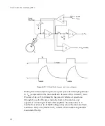
Figure
46.
DCC
Mode
block
diagram
and
timing
diagram.
During
the
current
‐
injection
period
a
square
pulse
of
current
proportional
to
V
cmd
is
injected
into
the
microelectrode.
Because
of
this
current
V
1
rises.
The
rate
of
rise
of
V
1
is
limited
by
the
parasitic
effects
of
capacitance
through
the
wall
of
the
glass
microelectrode
to
the
solution,
and
capacitance
at
the
input
of
the
buffer
amplifier.
The
final
value
of
V
1
reached
consists
mostly
of
the
IR
voltage
drop
across
the
microelectrode
resistance.
Only
a
tiny
fraction
of
V
1
consists
of
the
membrane
potential
recorded
at
the
tip.
90


