background image

User


Guide


for


Axoclamp


900A


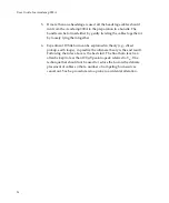
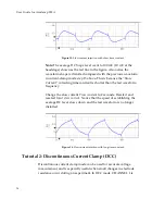
Figure


15.


Slow


current


injection


with


short


time


constant.


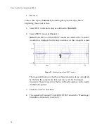
Note:


The


average


DC


Scope


level


went


to


100


mV


(10


mV


at


the


headstage)


shown


as


the


red


line


in


the


figure.


Also


notice


the


waveform


shape


is


distorted


compared


with


the


previous


waveform


in


current

clamp


mode


step


15


above.


This


is


because


the


“Slow


Current”


correcting


time


constant


is


shorter


than


the


test


waveform


frequency.


Change


the


slow


current


Time


constant


to


2


seconds.


Deselect


and


reselect


Inject


slow


current

.


Notice


that


the


speed


of


establishing


the


average


DC


level


slows


down


and


the


test


waveform


is


no


longer


distorted.


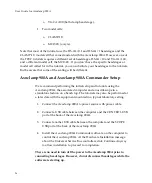
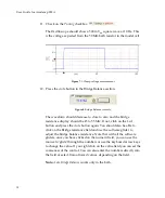
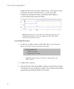
Figure


16.


Slow


current


injection


with


long


time


constant.


Tutorial


2:


Discontinuous


Current


Clamp


(DCC)


Discontinuous


current


clamp


mode


can


be


used


for


accurate


voltage


measurement,


and


is


especially


useful


when


small


changes


in


electrode


resistance


occur


during


an


experiment.


In


DCC


mode,


CHANNEL


1


is


34


Содержание Axoclamp 900A

Страница 1: ...rode Amplifier Molecular Devices Corporation Sunnyvale California 94089 Part Number 2500 0179 Rev A 800 998 MATE www autom8 com 6 50 Universit y Ave 5 Berkeley CA 9 4710 USA t e l 5 10 8 4 5 6 2 8 3 f...

Страница 2: ......

Страница 3: ...marks are the property of their respective owners Technical Assistance For technical assistance product comments and feedback or help to resolve a problem please visit Molecular Devices Technical Supp...

Страница 4: ......

Страница 5: ...iii...

Страница 6: ......

Страница 7: ...tions 8 Front Panel 8 Rear Panel 9 Overview 11 Axoclamp 900A Commander Interface Overview 12 Toolbar 12 Meters 13 Mode Buttons 13 Mode Tabs 14 Scaled Output Tabs 15 Setting Parameters in the Axoclamp...

Страница 8: ...l Cell 41 II TEVC Using the MCO 2U Oocyte Model Cell and VG 9A Bath Clamp 46 DC Restore 49 Tutorial 5 Auto Mode Switching 50 Example of Auto Mode Switching 51 Setup of Auto Mode 52 Tutorial 6 High Vol...

Страница 9: ...eability 77 Cleaning 77 Input Leakage Current 77 Input Resistance 78 Holders 78 Holder Design 78 Optional Ag AgCl Pellets 80 Holder Use 80 Holder Maintenance 81 Sharp Microelectrode Recording 82 Micro...

Страница 10: ...illation 123 Current Clamp 123 Voltage Clamp 124 Current Injection Resistor R0 124 Holding 124 How to Use Holding 125 Keyboard Shortcuts 125 Hot Keys 125 Shortcut Keys 125 Load Configuration 128 Mode...

Страница 11: ...ation 143 Limitations of Capacitance Neutralization 144 Oscillation Detection and Removal 144 Pipette Offset 144 How to Use Pipette Offset 145 Additional Notes 145 Pulse 145 How to Use Pulse 146 Addit...

Страница 12: ...l Notes 159 V Clamp Control 159 Gain 159 Lag 159 DC Restore 160 Chapter 6 Troubleshooting 161 Voltage Clamp Problems 162 dSEVC 162 TEVC 162 All Voltage Clamp Modes 163 Space Clamp 164 Noise 166 Chapte...

Страница 13: ...73 Auxiliary Inputs Outputs 2 off 173 Scaled Outputs 174 Metering 4 off 174 Audio Monitor 175 Performance Specification 175 I Clamp Channels 1 2 175 DCC Channel 1 175 HVIC Channel 2 176 dSEVC Channel...

Страница 14: ......

Страница 15: ...ble space in your electrophysiology setup By making the Axoclamp 900A computer controlled it enables us to add several powerful new features that make it easier to set up and run experiments and that...

Страница 16: ...ular is applications Amplifier performance is better than ever The 180 V output compliance used for TEVC and HVIC modes makes it possible to pass larger currents and ensures faster clamp speeds TEVC a...

Страница 17: ...e that could end experiments prematurely The Axoclamp 900A Commander interface is completely independent of acquisition software Thus the Axoclamp 900A can be used with any data acquisition package It...

Страница 18: ...ry and use of the Axoclamp 900A Any comments and suggestions on the use and design of the Axoclamp 900A will be much appreciated We welcome reprints of papers describing work performed with the Axocla...

Страница 19: ...he factory at a later date For the initial checkout the Axoclamp 900A should be situated on a bench top away from other equipment Do not install it in a rack until the checkout is complete Check List...

Страница 20: ...er to the computer for discontinuous mode operation 3 Connect the HS 9A headstage s to the CHANNEL 1 HEADSTAGE and CHANNEL 2 HEADSTAGE rear panel connectors The amplifier CAN be left on when changing...

Страница 21: ...days to check for a new download 3 Next you see the Select Device dialog In the Axoclamp tab select Axoclamp Hardware then click the Scan button The amplifier serial number is identified in the list...

Страница 22: ...is enabled when the user has checked one of the Switch to dSEVC TEVC on ext input checkboxes in the Headstage 1 or 2 section at the top of the Axoclamp 900A Commander For example a TTL Low 0 0 8 V in...

Страница 23: ...rent IC External Command Potential VC or External Command Current IC Auxiliary Potential if HS 9A headstage attached or Auxiliary Current if VG 9A headstage attached The same inputs and outputs are av...

Страница 24: ...e connectors with an appropriate optional adapter cable 1 2100 0934 10AUX1 OUTPUT and 10AUX2 OUTPUT These BNC outputs provide 10 output signal for the respective AUXILIARY HEADSTAGE channels REMOTE Mo...

Страница 25: ...puter to control the Axoclamp 900A SCOPE USB Connects to a USB 2 0 port of the host computer to provide Scope window data This is a self contained single channel 5 MHz acquisition system that allows t...

Страница 26: ...amp 900A Commander Interface Overview The Axoclamp 900A Commander front panel is designed to resemble hardware instrument controls It is divided into five main sections Toolbar Meters Mode buttons Mod...

Страница 27: ...hannel This can be activated in either voltage clamp or current clamp modes but not I 0 mode or with slow current injection Note that to measure resistance the Axoclamp 900A Commander generates a comm...

Страница 28: ...utput setting on the Options General tab External Mode Control The mode buttons can be operated from an external source Check the Switch to dSEVC on ext input or Switch to TEVC on ext input checkbox t...

Страница 29: ...s in the Axoclamp 900A Commander User configurable numerical fields on the Axoclamp 900A Commander printed in blue text are called gliders Placing the mouse over a glider changes the cursor to Click t...

Страница 30: ...hift boosts sensitivity by 10 and Ctrl by 100 then at Medium setting they increase sensitivity 20 and 200 times respectively while with a basic Coarse setting these are 50 and 500 times respectively K...

Страница 31: ...ending on the value displayed e g the Tuning amplitude field displays some values in pA and others in nA When typing in values you must always express the value in terms of the smaller unit You can ca...

Страница 32: ...y to toggle between window sizes Most other buttons are self explanatory with the possible exception of the Save Configuration F5 Load Configuration F4 and Quick Select buttons These buttons allow the...

Страница 33: ...1 I Clamp LED and the blue TEVC LED should light Check to see that the LEDs change with the modes selected in the software 4 If the USB cable is unplugged the STATUS LED flashes briefly ON then OFF M...

Страница 34: ...hniques and offset adjustment When the switch is in the CELL position both microelectrode resistors are effectively intracellular In Bridge or DCC mode you should see exponential voltage responses to...

Страница 35: ...ctrodes The circuit diagram is given below Figure 4 MCO 2U model cell Installation of Model Cells To install the model cell plug it into one or both of your headstages Connect the gold plated ground j...

Страница 36: ...pply transients glitches Although normally inconsequential glitches could cause transients to appear on the voltage and current outputs that may corrupt high sensitivity recordings The most effective...

Страница 37: ...to radiate into its electronics A thick sheet of steel placed between the Axoclamp 900A and the radiating equipment can effectively reduce the induced hum 3 Initially make only one connection to the A...

Страница 38: ...6 Experiment While hum can be explained in theory e g direct pickup earth loops in practice the ultimate theory is the end result Following the rules above is the best start The final hum level can of...

Страница 39: ...orial procedures require the following Axoclamp 900A main unit with power cord Two USB control cables Axoclamp 900A Commander software A PC running Windows 2000 or XP Professional External two channel...

Страница 40: ...Axoclamp 900A the associated computer and an oscilloscope in a standalone fashion on a bench top The tutorials may also be performed at a later date with the equipment mounted in a typical laboratory...

Страница 41: ...ge The switch should be in the BATH position 9 Place the headstage and model cell into a shielded enclosure optional ensuring that the shield is also connected to the signal ground 10 Turn the Axoclam...

Страница 42: ...Connect another BNC cable between the SCALED OUTPUT for Channel 2 and the oscilloscope 16 Connect another BNC cable between the external trigger input of the oscilloscope and the SYNC OUTPUT BNC on t...

Страница 43: ...wer ON 7 Run the Axoclamp 900A Commander software 8 Press the Reset to Program Defaults button in the toolbar at the top of the Commander and accept the warning Information about the connected headsta...

Страница 44: ...M If not click on the Lock button and press the Auto button again You should also be able to click on the Bridge resistance field and use the software glider to adjust the bridge balance resistance No...

Страница 45: ...ated electrode capacitance Figure 9 Bridge Balance of voltage signal in bath 14 Check the Pipette Capacitance Neutralization checkbox Change the value in the numeric field until the capacitive transie...

Страница 46: ...should not be done if this tutorial is being performed solely in preparation for another tutorial Oscillation Detection 16 Click Detect Oscillation and select Disable Neutralization Figure 12 Oscillat...

Страница 47: ...on checkbox Note Oscillation Detection is available in current clamp modes of IC and DCC but not HVIC It is also available in the two voltage clamp modes TEVC and dSEVC Slow Current Injection 17 Slow...

Страница 48: ...nstant is shorter than the test waveform frequency Change the slow current Time constant to 2 seconds Deselect and reselect Inject slow current Notice that the speed of establishing the average DC lev...

Страница 49: ...compared with I Clamp mode with Bridge Balance is that it is tolerant of small changes in microelectrode resistance The disadvantage is that DCC mode is noisier than I Clamp mode During DCC mode CHANN...

Страница 50: ...shape to the IC waveform except it will have about double the noise Figure 18 Membrane potential signal in DCC mode 4 Adjust the Pipette Capacitance Neutralization value and Rate in the I Clamp 1 tab...

Страница 51: ...compensated Figure 20 Pipette Capacitance Neutralization over compensated in DCC mode Tutorial 3 Discontinuous Single Electrode Voltage Clamp dSEVC dSEVC mode is used to voltage clamp small cells that...

Страница 52: ...ted the monitor waveform is displayed in the Scope window on the computer screen Figure 21 Monitor signal for dSEVC mode The important feature is that the voltage transients decay completely by the ti...

Страница 53: ...e with about a 20 ms rise time Note that we programmed a voltage of 10 mV but only got a 6 mV response indicating a higher gain is required Also the current trace IN1 shows a similar settling time In...

Страница 54: ...V and the rise time should be less than 300 s with noise around 10 mVp p See the expanded time scale below Figure 24 Voltage and current signals for dSEVC mode with further tuning 8 With practice you...

Страница 55: ...tion Figure 26 Monitoring the dSEVC voltage response with a second headastage IN0 is the membrane voltage as measured by Headstage 1 dSEVC mode IN1 is the membrane voltage as measured by Headstage 2 w...

Страница 56: ...UT to oscilloscope channel 2 3 Press the Reset to Program Defaults button and accept the warning 4 Connect a Headstage 1 to the ME1 input of the CLAMP 1U model cell b Headstage 2 to the ME2 input of t...

Страница 57: ...10 mV mV b Channel 2 Headstage 2 0 1 Membrane Current 1 V A 10 Adjust the Gain until channel 1 starts to overshoot The Rise time should be about 200 s Figure 27 Voltage and current signals for TEVC m...

Страница 58: ...e membrane current 1 V A The voltage clamp Gain is 388 Pipette Capacitance Neutralization is 3 5 pF Oscillation Detection 1 In the Detect oscillation section of the TEVC tab you can choose to Reduce g...

Страница 59: ...f a typical oscillation showing that it was detected and removed in about 2 ms Figure 31 Automated suppression of voltage signal oscillation in TEVC mode IN0 is 10 the membrane voltage Note Oscillatio...

Страница 60: ...gand gated channels low membrane resistance can lead to loss of tight voltage clamp when high current is passed This procedure explains how to overcome each of these problems Equipment required MCO 2U...

Страница 61: ...ton and accept the warning 6 Verify that the R0 value for Headstage 1 is 10 M and the R0 value for Headstage 2 is 1 M 7 Zero the Pipette Offset for Channels 1 and 2 outlined in the Current Clamp secti...

Страница 62: ...set the Lag to about 0 2 ms 14 Select TEVC mode 15 For the SCALED OUTPUT signals select a Channel 1 Headstage 1 Membrane Potential 10 mV mV b Channel 2 Headstage 2 0 1xMembrane Current 0 1 V A 16 Turn...

Страница 63: ...ring the voltage pulse increases channel 2 on the oscilloscope by about 450 mV 4 5 A and the voltage clamp voltage drops to about 48 mV due to the extra load DC Restore DC Restore provides optimal vol...

Страница 64: ...ddition to manually controlled mode switching from Axoclamp 900A Commander Axoclamp 900A has the ability to automatically switch between I Clamp and V Clamp modes and back again Auto mode switching al...

Страница 65: ...lowing switches from I Clamp to TEVC mode when membrane voltage in headstage 1 passes through 20 mV in a negative to positive direction It stays in TEVC mode for 500 ms generating a 0 mV to 10 mVp p 1...

Страница 66: ...mp 2 tab set the TUNE input for Headstage 2 to 1 nA 6 Oscilloscope Channel 1 should show a 50 400 mV triangular wave with rounded sides This equates to a 5 40 mV waveform that will trigger the mode ch...

Страница 67: ...rn to I Clamp after 500 ms In order to monitor mode changes on the scope we need to program the SYNC BNC to follow mode changes 7 Click on the General tab 8 In the Sync Output group click the Mode rad...

Страница 68: ...veforms should result Figure 36 Automated Mode Switching signals IN0 is 10 the membrane potential in Channel 1 IN1 is the Mode signal HIGH is V Clamp mode and LOW is I Clamp mode Explanation of the wa...

Страница 69: ...o the preparation or electrode resistance is very high For example if you want to pass 1 A current into the CLAMP 1U model cell it requires more than 100 V of dynamic range for the driving electrode T...

Страница 70: ...al selected should be Headstage 2 0 1 Membrane Potential 9 Connect scope channel 2 to SCALED OUTPUT 2 10 The Channel 2 SCALED OUTPUT Signal selected should be Headstage 2 0 1 Membrane Current Figure 3...

Страница 71: ...lect Membrane Potential 1 mV mV Figure 38 Bridge Balance settings 14 Check Bridge Balance and balance bridge 50 M Figure 39 HVIC mode with Bridge Balance 15 HVIC with Bridge Balance 50 1 M The 1 ms sp...

Страница 72: ......

Страница 73: ...perienced researchers working in laboratories around the world However as is the case for all advice and particularly that pertaining to research the suggestions given here should be taken as provisio...

Страница 74: ...s and neither are they tolerant of large drifts in the tissue or electrode that tend to pull the electrode out of the cell For this reason it is important to use a good drift free micromanipulator for...

Страница 75: ...00A Commander This displays on the meter the pipette voltage required for zero current through the electrode If for instance the meter shows 2 mV there has been a 2 mV drift since the electrodes were...

Страница 76: ...rd that is provided with the interface Finally it is necessary to install software to control the interface Software is available from Molecular Devices pCLAMP or other vendors or you can write your o...

Страница 77: ...resistive load the noise is given approximately by 12 R Vrms 10 kHz bandwidth where R is the parallel combination of the current injection resistor R0 and the load resistance i e the electrode resista...

Страница 78: ...determined by the effectiveness of the Capacitance Neutralization circuit Compensation Circuits V Clamp Increasing Voltage Clamp Control Gain is required for optimal voltage control and bandwidth but...

Страница 79: ...ng very large cells such as Xenopus oocytes in which case the ionic current may be of the order of several microamperes or even several tens of microamperes Depending upon the method of grounding the...

Страница 80: ...it is relatively small On the other hand the resistance of the grounding pellet and agar bridge are larger but one can take precautions to minimize them A 1 mm diameter Ag AgCl pellet in Ringer s sol...

Страница 81: ...can actually measure Rb in Bridge mode by placing both micropipettes in the bath Put the micropipette connected to CHANNEL 1 on the far side of the micropipette connected to CHANNEL 2 away from the ba...

Страница 82: ...espective of the voltage drop across Rb1 This configuration is particularly recommended for voltage clamping oocytes The VG 9A 100 bath clamp is required for the fastest responses and guaranteed stabi...

Страница 83: ...and subtracted from the measurements made by CHANNEL 1 and CHANNEL 2 The voltage recorded by the bath microelectrode is available at the SCALED OUTPUT signal BNC on the front panel You can select thes...

Страница 84: ...th each Axoclamp 900A amplifier HS 9A 0 1 and HS 9A 1 Other headstages may be substituted on request at the time of purchase All headstages record voltage at unity gain Several headstage current gains...

Страница 85: ...f which is the pipette voltage Vp A2 is a summing amplifier used for injecting current into the cell The voltage across the headstage resistor R0 is equal to Vcmd regardless of Vp Thus the current thr...

Страница 86: ...old plated 1 mm plug on the rear of the headstage The bath should not contact any other ground e g Signal Ground Static Precautions The headstage can normally be safely handled However if you are in a...

Страница 87: ...one the Axoclamp 900A Commander recognizes the headstage as a custom type and prompts for current injection resistance and capacitance values This message appears on startup of the Commander Once a cu...

Страница 88: ...nsitivity to current commands the sensitivity of the current monitors and the gain in SEVC mode Since the effects always appear in multiples of ten they are easy to calculate For your convenience Tabl...

Страница 89: ...es use the largest feasible H value This is because the current passing response is best with low values of R0 2 A limitation on using large H values is that as R0 becomes smaller the input leakage cu...

Страница 90: ...uate performance even if R0 is as small as 1 10 or as large as 10 Re USE RECOMMENDATION NORMAL INTRACELLULAR BRIDGE RECORDING Follow the general rule EXTRACELLULAR RECORDING Since there is no current...

Страница 91: ...Avoid spilling liquids on the headstage Input Leakage Current All DC connected systems suffer from the problem of drift With changes in temperature and the passage of time the DC transfer functions of...

Страница 92: ...er possible factors which would decrease the input resistance are minimized For example the field effect transistor FET input of the headstage is referenced to the input voltage rather than to ground...

Страница 93: ...r The holder mates with the threaded Teflon connector on U type Molecular Devices headstages and is secured in place with a threaded collar Figure 44 Exploded view of the HL U holder The bore size of...

Страница 94: ...inner diameter ID of the pipette must be 1 mm A wax sealed Teflon tube surrounds the silver wire This ensures that the electrode solution only contacts the Ag AgCl pellet Three pellet assemblies are s...

Страница 95: ...er wire down to the bare metal using fine sand paper and immerse the cleaned wire in bleach for about 20 minutes until the wire is uniformly blackened This provides a sufficient coat of AgCl to work r...

Страница 96: ...ffer advantages In this chapter it is assumed for the most part that sharp microelectrodes are being used for the I Clamp recording Microelectrode Properties Users of sharp microelectrodes spend far m...

Страница 97: ...tance The settling time of a microelectrode depends not only on Re but also on the transmural capacitance Ct from the inside of the microelectrode to the external solution For fastest settling Ct must...

Страница 98: ...terial This can be done just before use by dipping the filled microelectrode into a fluid such as silicone oil or mineral oil Another method is to coat the microelectrode with Sylgard 184 or Q dope mo...

Страница 99: ...croelectrode is pressed into an unvented holder The suction port on the HL U series holders provided with the Axoclamp 900A should therefore be left open Using filling solutions with low pH or adding...

Страница 100: ...ton to null the offset Check the stability of the bath electrode and microelectrode Drifts in Scaled Output Membrane Potential indicates that the electrode wires probably need to be rechlorided Also c...

Страница 101: ...arger reflecting the membrane time constant and input resistance After impaling the cell it is often helpful to back off the microelectrode slightly and allow the penetration to stabilize for a few mi...

Страница 102: ...HANNEL 1 is memorized by a sample and hold circuit in between each current passing period after all transient voltages due to current passing have decayed Thus the membrane potential can be recorded i...

Страница 103: ...Vcmd position This connects Vcmd to a differential amplifier A4 arranged so that its output is V1 Vcmd The voltage appearing across R0 is exactly equal to Vcmd thereby forcing the current I0 into the...

Страница 104: ...e of this current V1 rises The rate of rise of V1 is limited by the parasitic effects of capacitance through the wall of the glass microelectrode to the solution and capacitance at the input of the bu...

Страница 105: ...and this average value is available on the Scaled Output Headstage 1 Membrane Current signal During DCC mode the input to the CCS and the output of the CHANNEL 1 current monitor are automatically sca...

Страница 106: ...ifier A2 The output of this amplifier becomes the input of a controlled current source CCS if the switch S1 is in the current passing position The gain of the CCS is GT The CCS injects a current into...

Страница 107: ...ach cycle and voltage recording for 70 of each cycle The cycling rate sample rate must be chosen so that there are ten or more cycles per membrane time constant This enables the membrane capacitance t...

Страница 108: ...is too slow the dSEVC becomes unstable This is because the long current passing period charges the membrane potential past the desired potential before the clamp has an opportunity to take a new sampl...

Страница 109: ...f G will have to be used to maintain stability Clamp Error With finite gains in the voltage clamp circuit Vm does not quite follow Vc The error is Vcmd Vm Similarly if Vcmd is constant and the cell me...

Страница 110: ...orded The added consequence is that Rs limits the maximum rate at which the membrane can be charged To eliminate Rs altogether watch the MONITOR output and make sure the transient decays completely be...

Страница 111: ...where primary efforts have been taken to keep the input capacitance low to much larger factors in systems where large amounts of capacitance to earth and capacitance to shield are tolerated The secon...

Страница 112: ...he records is by averaging repetitive responses This well known procedure reduces the noise by the square root of the number of averages without affecting the time course of the signal Although the no...

Страница 113: ...e Pipette Capacitance Neutralization setting of CHANNEL 1 affects the voltage clamp response The Seal Test setting delivers a voltage pulse The best settings of the voltage clamp parameters are found...

Страница 114: ...ted using microelectrodes of comparable resistance even given the higher frequency response of the TEVC The major drawbacks to TEVC systems are that two microelectrodes must be applied to one cell and...

Страница 115: ...a detailed discussion of this type of series resistance and the methods used to minimize it see Bath Error Potentials on page 65 Selection of the Membrane Voltage Recording Headstage CHANNEL 1 Usually...

Страница 116: ...ugh compliance to fully resolve these large transients Table 4 summarizes the current passing capability of the HS 9A headstages Headstage R0 M Short Circuit Current Conversion HS 9A 0 1 100 1 8 A 100...

Страница 117: ...the current passing microelectrode Tuning the Voltage Clamp Fidelity and Stability The object of tuning the voltage clamp is to maximize the feedback gain There are two reasons first the bandwidth of...

Страница 118: ...xponentially towards its new value For K 1 the time constant for the relaxation is C R m e 2 Increasing the clamp gain decreases the time constant for the step response For example if Re2 10 M Cm 1000...

Страница 119: ...1 Inter Electrode Coupling Capacitance and Shielding When the voltage recording microelectrode and current passing microelectrode are applied to a cell there is considerable coupling capacitance Cx be...

Страница 120: ...the high frequency measurement of the current unless the capacitance neutralization of CHANNEL 2 is properly set Under these circumstances the capacitance neutralization of CHANNEL 2 may have a signif...

Страница 121: ...chnique such as measuring the current using the macropatch technique might be considered It is good practice to keep the tips of the two intracellular microelectrodes as far apart as possible inside t...

Страница 122: ...the Scaled Output of the Axoclamp 900A are 4 pole filters Filters with more poles can be constructed but they are more complex to implement and yield diminishing returns Figure 48 Filter characterist...

Страница 123: ...ortant considerations when selecting the filter cutoff frequency Aliasing If the digitizing interface samples at 2 kHz for example any noise in the sampled signal that has a frequency greater than 1 k...

Страница 124: ...han 0 4 ms so the action potentials are minimally distorted by the filter According to the above equation then the appropriate filter setting would be 10 kHz In practice you may need to make other com...

Страница 125: ...ing period ends Usually this deviation is preferable to the situation that can occur if Blanking is not used If Blanking is not used the artifact picked up by CHANNEL 1 is treated by the voltage clamp...

Страница 126: ...le current into the bath can be separately measured using a virtual ground headstage see below Virtual Ground Current Measurement A Virtual Ground headstage can be used to ground the preparation bath...

Страница 127: ...ent as line frequency noise in the current signal Saline filled tubing acts as an excellent antenna To prevent them carrying hum long saline filled tubes should have the saline pathway broken by an ai...

Страница 128: ......

Страница 129: ...dix describing Polarity Conventions This summarizes the conventions used for the polarities of currents and voltages in all amplifiers manufactured by Molecular Devices Always On Top Always On Top F3...

Страница 130: ...s the adjustable field to the resistance it is compensating for and checks the checkbox Auto can be used whether or not Bridge Balance has already been activated You can fine tune the resistance value...

Страница 131: ...epped to a new value top there is a rapid voltage step on Vp due to the ohmic voltage drop across the microelectrode middle Following this instantaneous step there is a slower rise in Vp largely due t...

Страница 132: ...nuously through the experiment by injecting a small current step near the beginning of each data sweep It is recommended that Pipette Capacitance Neutralization be set at the same time as Bridge Balan...

Страница 133: ...on is achieved by increasing the Pipette Capacitance Neutralization by a small amount over the currently set level Therefore it is essential that you set Pipette Capacitance Neutralization to the corr...

Страница 134: ...one extracellularly Penetrating cells Sometimes microelectrode tips press against the cell membrane but fail to penetrate A quick press on the Clear buttons will often force the electrode to penetrate...

Страница 135: ...the device the SoftPanel tool button is disabled Default SoftPanel Settings See below for the default SoftPanel settings for the Axoclamp 900A These settings can be customized to the individual user F...

Страница 136: ...meter that is currently selected in Commander in increments equivalent to a knob click with Shift Page Down Decreases the parameter that is currently selected in Commander in increments equivalent to...

Страница 137: ...s you with options to protect your cell from harmful oscillations during a current clamp experiment by automatically disabling or reducing Pipette Capacitance Neutralization Use the Detect Oscillation...

Страница 138: ...are suppressed by changing the Gain setting Current Injection Resistor R0 The current injection resistor in the headstage is automatically detected and displayed in the R0 field at the top of the Hea...

Страница 139: ...essed in units of nA Check the Holding checkbox to apply the holding current or potential Settings can be adjusted after the command has been activated Uncheck the checkbox to stop the holding current...

Страница 140: ...ope F11 Channel 1 Scaled Output Scope Shift F11 Quick Select Button 1 Ctrl 1 Quick Select Button 2 Ctrl 2 Quick Select Button 3 Ctrl 3 Meters and Mode Selection Headstage 1 Total Resistance Rt Ctrl R...

Страница 141: ...ro Scaled Zero Ctrl Shift O letter V Clamp Tab Zero Scaled Output Ctrl Shift O letter Pulse Ctrl Shift P Keystroke Function Adjustable Numerical Fields Up Arrow Increases value For dual control field...

Страница 142: ...active field Ctrl Tab Go to next tab Shift Ctrl Tab Go to previous tab Arrow Move between options in non numerical fields Adjust values in numerical fields see above Adjustable Numerical Fields Space...

Страница 143: ...when it is configured for external switching allows you to switch between current and voltage clamp modes with a remote device e g a Clampex digital output for one channel at a time Alternatively the...

Страница 144: ...mbrane potential threshold is configured on the Options Auto tab When automatic mode switching is configured the Mode Switch label changes to Switch to dSEVC TEVC at threshold but the automatic switch...

Страница 145: ...ignal when the Shift key is held down The corresponding shortcut is Shift F11 Options The Options F10 dialog box has five tabs on which many Commander parameters are set The Options tabs are Options G...

Страница 146: ...gs 20 mV V and OFF 20 mV V means that a 1 V step applied to the COMMAND BNC appears to the cell as a 20 mV step i e external commands are divided down by 50 fold This setting should be used when you w...

Страница 147: ...utput Lowpass Filter Sync Output The SYNC OUTPUT BNC on the rear panel of the Axoclamp 900A outputs a TTL signal HIGH 2 5 V LOW 0 0 8 V synchronized with the feature selected in this section This can...

Страница 148: ...tion reports the headstage types and the gain they apply prior to gain applied with the gain settings in the Axoclamp 900A Commander interface Signals from both auxiliary headstages are available for...

Страница 149: ...return to current clamp after a change to voltage clamp are at the bottom of the section Changes are not triggered from I 0 mode You can synchronize a TTL output signal to amplifier mode selection wi...

Страница 150: ...Switch to dSEVC TEVC at threshold You must configure the delay field below for any of these selections and configure the membrane potential threshold field if you have selected a threshold option Dela...

Страница 151: ...tion However you must ensure that when the Axoclamp first switches to voltage clamp the external TTL signal is HIGH so that a change to LOW triggers a return to current clamp at the correct time Manua...

Страница 152: ...he Axoclamp 900A with the possibility of causing damage to its circuitry Mute Check this option to mute the audio monitor Volume Use the slide to set the volume of the audio monitor right to increase...

Страница 153: ...output for each channel in each mode Whether you hear Channel 1 or Channel 2 at any time depends on which tab is uppermost on the front panel If a Channel 1 tab is on top the Channel 1 output is audi...

Страница 154: ...nd DSP Firmware This information is automatically displayed A link to the Axoclamp 900A Commander Update page at Molecular Devices web site Users are advised to check this page at regular intervals to...

Страница 155: ...The Zero Output Offset only affects the signal on the Scaled Output In other words the cell is not affected by the Output Offset command No other input or outputs are affected The offset is reported...

Страница 156: ...ound of the microelectrode and any connecting lead Cin2 Cin combined with the microelectrode resistance Re acts as a lowpass filter for signals recorded at the tip of the microelectrode For optimal pe...

Страница 157: ...ssible The technique is known as bootstrapping Unity gain feedback is used to reduce the component of stray capacitance that exists between the amplifier input and its power supplies and case Sophisti...

Страница 158: ...ce the neutralizing circuit adds noise to the voltage signal It is important to recognize that the capacitance neutralization circuit is not more than 90 effective even for ideal microelectrodes This...

Страница 159: ...250 mV The glider control allows fine adjustments with increments of 20 V for current clamp To reset the Pipette Offset click on the locked padlock button to unlock it and click the Zero button again...

Страница 160: ...onal Notes Pulse generates a Sync Output Quick Select The three Quick Select buttons can be customized to Open saved Configuration files acc of Axoclamp 900A Commander Run an executable file on your c...

Страница 161: ...2 resizes the Axoclamp 900A Commander interface It toggles the interface between three states Full display the whole interface is shown Meter panel only the toolbar meters and mode buttons are shown M...

Страница 162: ...with Load Configuration Quick Select or by using a desktop shortcut command line switch See Load Configuration Scaled Output The Scaled Output field is located in the lower part of each of the I Clam...

Страница 163: ...note below Auxiliary 2 Current Current from the rear panel AUXILIARY HEADSTAGE 2 connection see note below Current Clamp The signals available in current clamp are Membrane Potential Membrane Potenti...

Страница 164: ...xiliary headstages at the AUXILIARY 1 HEADSTAGE and AUXILIARY 2 HEADSTAGE inputs typically as headstages for extracellular recordings The scale factor determined by the headstage is displayed beside t...

Страница 165: ...m the right click popup menu to set the cutoff frequency desired Filtering begins immediately Set the field to DC to bypass this filter Gain Scaled Output Gain is in the Scaled Output section in the l...

Страница 166: ...e filter type The Axoclamp 900A Commander offers a choice of two different lowpass filters to the Scaled Output Bessel or Butterworth Select these on the Options General tab Different cutoff frequency...

Страница 167: ...e in order to monitor some parameter in your experimental setup You can choose potentials from 0 to 1000 mV Discrete frequency settings between 2 and 5000 Hz are available View the options by right cl...

Страница 168: ...900A Commander software to your Axoclamp 900A amplifier If you want to run more than one Axoclamp 900A amplifier at a time simply open a new instance of the Axoclamp Commander for each amplifier and s...

Страница 169: ...l Tab Use this tab to associate a SoftPanel with Axoclamp 900A Commander Scan Click the Scan button to search all serial and USB ports for SoftPanels Results are displayed in the Port field Once you h...

Страница 170: ...ng The speed at which current is injected into the cell depends on the current injection resistor and load as well as the setting in the Time constant field The time constant values shown in the glide...

Страница 171: ...ange of its parameter settings These telegraphs are handled by the program using the Windows messaging system The benefit of this is that no additional telegraph cabling is required the computer conne...

Страница 172: ...current injection resistor selected Injection Resistor Current Amplitude 1 M 12 A 10 M 1 2 A 100 M 120 nA Table 8 Headstage current amplitude range Frequency settings for Tuning range in discrete valu...

Страница 173: ...cy response of the voltage clamp circuit can be modified by the Lag control The voltage clamp circuit can thereby be adjusted to compensate for the non ideal phase response of real membranes The contr...

Страница 174: ...but variable input leakage current is due to DC current flow through the dielectric of the capacitor C used for pipette capacitance neutralization For example the pipette potential might be 200 mV al...

Страница 175: ...nected to the Axoclamp 900A except for the oscilloscope Ideally remove the Axoclamp 900A from the rack Work through the Seup and Tutorials This can often uncover a problem that is in your setup If the...

Страница 176: ...se The inter electrode coupling capacitance may be too high Suggestion Check that the shield between the microelectrodes is correctly placed and adequately grounded Symptom The voltage clamp is slow t...

Страница 177: ...quired to drive the same current If the problem lies in the virtual ground unit use another one with higher range All Voltage Clamp Modes Symptom Unable to offset the voltage microelectrode voltage to...

Страница 178: ...causes 1 A large series resistance or 2 the cell is not isopotential The latter is common when you voltage clamp a neuronal soma with an axon and dendrites attached The slower components in the curre...

Страница 179: ...istorted As a general rule the voltage clamp is considered to be acceptable if the length of the attached axon or dendrites is no more than 0 1 length constants Even this short length will cause signi...

Страница 180: ...contributing noise sources must be minimized Specifically the headstage the pipette glass the holder and in the case of patch pipettes the membrane seal contribute significant noise even under circum...

Страница 181: ...ss otherwise specified TA 20o C 1 hr warm up time Main Unit Line voltage universal 100 240 VAC Line frequency 50 60 Hz Power 30 W maximum Fuse 5 mm 20 mm 250 V 2A slow Case H W L 4 3 19 14 3 109 mm 48...

Страница 182: ...0 10 M HS 9A 10 unity gain voltage follower R0 1 M VG 9A 10 bath clamp R0 1 M VG 9A 100 bath clamp R0 0 1 M Ro is the current passing resistor in the headstage Output Compliance CHANNEL 1 12 V in all...

Страница 183: ...n I Clamp and DCC Oscillation correction reduces neutralization by 1 pF Optionally it can reduce neutralization to zero SEVC and TEVC Oscillation correction reduces voltage clamp gain by 2 1 Optionall...

Страница 184: ...manual up to 0 5 s Step Activate Available on each channel STEP ACTIVATE 1 and STEP ACTIVATE 2 inputs work independently setting external timing for going between the holding level and a programmable...

Страница 185: ...ate 2 kHz to 5 MHz Resolution 14 bits Monitor signal Raw membrane potential before sample and hold PC display PC digital scope that is launched whenever DCC or dSEVC is selected It can be inhibited an...

Страница 186: ...ogrammable 20 ms to 2 s Test level Up to 10 R0 e g 10 A for HS 9A 10 Test Frequency 2 Hz to 5 kHz includes exact 50 Hz and 60 Hz Holding level Up to 1 R0 e g 1 A for HS 9A 10 dSEVC Test level Up to 4...

Страница 187: ...el 1 I CLAMP Command BNC Command gain V 10 R0 e g 100 nA V for HS 9A 10 TEVC V CLAMP Command BNC Command gain 20 mV V HVIC Channel 2 I CLAMP Command BNC Command gain V R0 e g 1000 nA V for HS 9A 10 Ex...

Страница 188: ...or VG 9A 100 Output Calibration 1 A V for VG 9A 100 Since there is a fixed gain of 10 1 the BNC output saturates at 1 10th of the maximum current but clamp continues to operate up to the maximum speci...

Страница 189: ...d Oscillator VCO VCO 100 mV 500 Hz 0 mV 2400 Hz 100 mV 4000Hz Level Programmable volume up to 1 Vp p Output Impedance 500 short circuit protected Noise 1 mVrms Performance Specification I Clamp Channe...

Страница 190: ...ent settling time2 500 s to 10 of peak value Voltage noise2 180 Vrms Current noise2 0 30 nArms TEVC Channels 1 2 together Internal holding level 200 mV AC voltage clamp gain 20 to 50 000 Voltage clamp...

Страница 191: ...rent noise 70 nArms 3 Model cell with two 1 M resistors to simulate the electrode resistances and a 1 M resistor and 220 nF capacitor in parallel to simulate the oocyte membrane Lowpass filter 10 kHz...

Страница 192: ......

Страница 193: ...1988 Finkel A S and Redman S J Optimal voltage clamping with a single microelectrode Voltage and Patch Clamping with Microelectrodes Smith T G Lecar H Redman S J Gage P W eds Williams Wilkins Baltimo...

Страница 194: ...od for perforated patch recordings using nystatin fluorescein mixture Jap J Physiol 43 267 273 1993 Microelectrodes Purves R D Microelectrode Methods for Intracellular Recording and Iontophoresis Acad...

Страница 195: ...mp recordings from neurons of the mammalian central nervous system Pfl gers Arch 414 600 612 1989 Finkel A S Progress in instrumentation technology for recording from single channel and small cells Mo...

Страница 196: ...nels detected with a new patch clamp configuration Nature 348 545 547 1990 Sakmann B and Neher E Single Channel Recording Plenum Press New York 1983 Wilson W A and Goldner M M Voltage clamping with a...

Страница 197: ...olecular Devices will be pleased to supply them to you However we caution you that the Axoclamp 900A is a sophisticated instrument and that service should only be undertaken by talented electronics ex...

Страница 198: ...uit diagrams and parts lists for the Axoclamp 900A I agree that I will only use the circuit diagrams and parts lists for service of the Axoclamp 900A I will not use them to create equivalent or compet...

Страница 199: ...900A can be directly connected to all international supply voltages The input range is from 100 to 240 V No range switching is required Alternatively the instrument can be powered by a DC voltage of...

Страница 200: ...should touch a grounded metal object immediately before touching the headstage Shipping the Axoclamp 900A The Axoclamp 900A is a solidly built instrument designed to survive shipping around the world...

Страница 201: ...tourner le support du fusible dans le sens oppos des aiguilles d une montre 3 Remplacer le fusible par un fusible de m me valeur 4 Rebrancher la prise de courant Installation du mat riel et s curit 1...

Страница 202: ...elui ci n est plus disponible il est recommand d envelopper soigneusement le Axoclamp 900A dans au moins trois inches 75 mm de mousse ou de feuilles d emballage bulles Le Axoclamp 900A ainsi prot g de...

Страница 203: ...ung das Netzkabel ausschalten Vor dem Auswechseln der Sicherung den Grund f r ihren Ausfall untersuchen Schritte zum Auswechseln der Sicherung 1 Das Netzkabel ausschalten 2 Die Fassung der Sicherung m...

Страница 204: ...ent das beim weltweiten Versand keinen Schaden nehmen sollte Um jedoch Versandsch den zu verhindern mu der Axoclamp 900A ordnungsgem verpackt werden Im allgemeinen l t sich der Axoclamp 900A am besten...

Страница 205: ...lla Para cambiar el fusible 1 Desconecte el cord n el ctrico 2 Use un destornillador o un dispositivo similar para girar el portafusibles en sentido contrario al de las manecillas del reloj 3 Reemplac...

Страница 206: ...Axoclamp 900A debe empacarse adecuadamente En general la mejor manera de empacar el Axoclamp 900A es en la caja original de f brica Si sta ya no se encuentra disponible le recomendamos que envuelva cu...

Страница 207: ...the cell membrane from the outside surface to the inside surface Outward Current Current that flows from the inside to the outside surface of the cell Membrane Potential The potential inside the cell...

Страница 208: ...e determined during subsequent data analysis Positive Current Current that flows out of the headstage into the electrode and out of the electrode tip into the cell Positive Negative Potential A positi...

Страница 209: ...clamp dSEVC Discontinuous single electrode voltage clamp fs Sampling rate rate for switching from current passing to voltage recording in DCC and dSEVC modes G The average gain during dSEVC GT The in...

Страница 210: ...with R0 R0 Current injection resistance Rs Resistance in series with membrane RMP Resting membrane potential Rm Rin Input resistance of cell membrane SEVC Single electrode voltage clamp TA Ambient tem...

Страница 211: ...btracting Vb 68 Minimizing 66 Blank Activate 10 Blanking 110 Bridge Balance 87 115 116 118 119 141 144 Buzz 87 119 120 Capacitance Neutralization 64 83 86 87 118 119 142 143 144 Chamber Design 59 Chas...

Страница 212: ...Leakage Current 77 Input Resistance 78 Interchangeability 77 VG 9A 70 High Voltage Current Clamp HVIC Mode 2 55 Holder Pipette Use 22 142 144 185 191 Holders 78 Ag AgCl Pellets 80 Cleaning 81 Design...

Страница 213: ...l Test 11 110 132 153 Select Device 154 Setup 25 26 Sharp Microelectrode Recording 82 Signal Ground 10 Slow Current Injection 156 Soft Panel Configure 120 Space Clamp 164 Sync Output 11 133 Telegraphs...

Отзывы: