Setup
and
Tutorials
9.
Connect
the
headstage
from
CHANNEL
2
to
the
ME2
input
of
the
CLAMP
‐
1U
model
cell
and
select
the
“Headstage
2,
Membrane
Potential
(10
mV/mV)”
signal
in
the
Channel
2
SCALED
OUTPUT
section.
The
Channel
2
headstage
will
now
serve
as
a
cell
membrane
voltage
monitor.
You
should
see
that
the
Channel
2
SCALED
OUTPUT
signal
is
identical
to
the
Channel
1
SCALED
OUTPUT
from
Headstage
1
(100
mV
p-p
)
as
below.
Channel
2
speed
will
be
slightly
slower
due
to
capacitance
loading.
You
can
speed
it
up
by
optimizing
Headstage
2
neutralization.
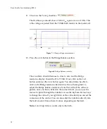
Figure
26.
Monitoring
the
dSEVC
voltage
response
with
a
second
headastage.
IN0
is
the
membrane
voltage
as
measured
by
Headstage
1
(dSEVC
mode).
IN1
is
the
membrane
voltage
as
measured
by
Headstage
2
with
2.5
pF
Pipette
Capacitance
Neutralization.
Tutorial
4:
Two
‐
Electrode
Voltage
Clamp
(TEVC)
I.
TEVC
Using
the
CLAMP
‐
1U
Model
Cell
Two
‐
Electrode
Voltage
Clamp
is
preferred
to
discontinuous
Voltage
Clamp
(dSEVC)
as
it
delivers
a
faster,
lower
noise
and
a
more
stable
voltage
clamp.
However,
it
requires
two
electrodes
to
be
inserted
into
the
same
cell,
which
is
more
difficult
in
smaller
cells.
Headstage
1
is
always
the
“voltage
monitoring”
electrode
and
Headstage
2
is
always
the
“current
‐
passing”
electrode.
Equipment
required:
CLAMP
‐
1U
model
cell.
41


