User
Guide
for
Axoclamp
900A
HS
‐
9A
×1.
Follow
the
steps
of
Tutorial
1
(excluding
the
optional
steps)
before
beginning
these
instructions.
1.
Select
DCC
mode
and
setup
as
outlined
in
Tutorial
2
.
2.
Select
dSEVC
mode
in
Channel
1.
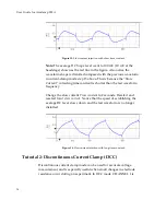
Note:
When
DCC
and
then
dSEVC
modes
are
selected
the
“monitor”
waveform
is
displayed
in
the
Scope
window
on
the
computer
screen.
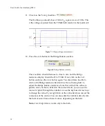
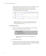
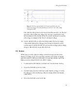
Figure
21.
Monitor
signal
for
dSEVC
mode.
The
important
feature
is
that
the
voltage
transients
decay
completely
by
the
time
the
samples
are
taken
(arrow)
even
for
the
largest
transients.
These
traces
show
that
switching
frequency
can
be
nearly
doubled
if
required.
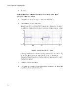
3.
Click
the
Seal
Test
checkbox.
4.
The
signal
for
Channel
1
SCALED
OUTPUT
should
be
“Headstage
1,
Membrane
Potential
(10
mV/mV)”.
38

