User
Guide
for
Axoclamp
900A
15.
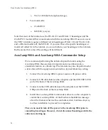
Move
the
CLAMP
‐
1U
switch
to
the
CELL
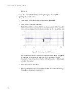
position.
The
waveform
should
be
about
400
mV
p-p
,
a
triangle
wave
with
exponential
sides.
Figure
11.
Compensated
I
‐
Clamp
voltage
signal.
The
following
two
steps
should
not
be
done
if
this
tutorial
is
being
performed
solely
in
preparation
for
another
tutorial.
Oscillation
Detection
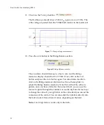
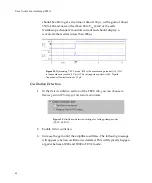
16.
Click
Detect
Oscillation
and
select
Disable
Neutralization
:
Figure
12.
Oscillation
detection
controls
for
I
‐
Clamp
mode.
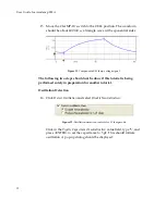
Click
in
the
Pipette
Capacitance
Neutralization
value
field,
type
‘5’,
and
press
<ENTER>
to
set
the
capacitance
to
5
pF.
This
should
initiate
oscillation.
A
pop
‐
up
dialog
should
be
displayed:
32


