4 - 3 4 - 3
MELSEC-Q
4 DATA USED FOR POSITIONING CONTROL
4.1.2 Setting items for parameters
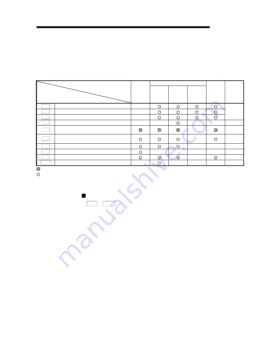
The table below lists items set to the positioning parameters. Setting of parameters is
similarly done for individual axes for all controls achieved by the QD70.
For details of controls, refer to SECTION 2 "CONTROL DETAILS AND SETTING". For
details of setting items, refer to "4.2 List of parameters".
Positioning control
Control
Parameter
OPR
control
Position
control
Speed-
position
switching
control
Current
value
changing
JOG
operation
Related
sub
function
Pr. 1
Software stroke limit upper limit value
–
Pr. 2
Software stroke limit lower limit value
–
Pr. 3
Software stroke limit valid/invalid setting
–
Section
11.4
Pr. 4
Current feed value during speed control
–
–
–
–
–
Pr. 5
Speed limit value
–
Section
11.2
Pr. 6
Bias speed at start
–
Section
11.5
Pr. 7
Positioning complete signal output time
–
–
–
Pr. 8
Deviation counter clear signal output time
–
–
–
–
–
Pr. 9
PULSE/SIGN method selection setup/hold time
–
–
Pr. 10
Stop mode during path control
–
–
–
–
–
: Always set
: Set as required (Read "–" when not required.)
–
: Setting not required. (This is an irrelevant item, so the set value will be ignored. If the value is the default value or within the setting
range, there is no problem.)
Checking the parameters
Pr. 1 to Pr. 10 are checked for the setting ranges when the "PLC READY signal
(Y0)" output from the PLC CPU to the QD70 changes from OFF to ON. At this time,
an error occurs in the parameter whose value has been set outside the setting
range. (For details, refer to "CHAPTER 13 TROUBLESHOOTING".)
Содержание GX Configurator-PT
Страница 13: ...MEMO SECTION 1...
Страница 127: ...7 20 7 20 MELSEC Q 7 SEQUENCE PROGRAM USED FOR POSITIONING CONTROL MEMO...
Страница 129: ...MEMO SECTION 2...
Страница 221: ...Index 5 Index 5 MEMO...


