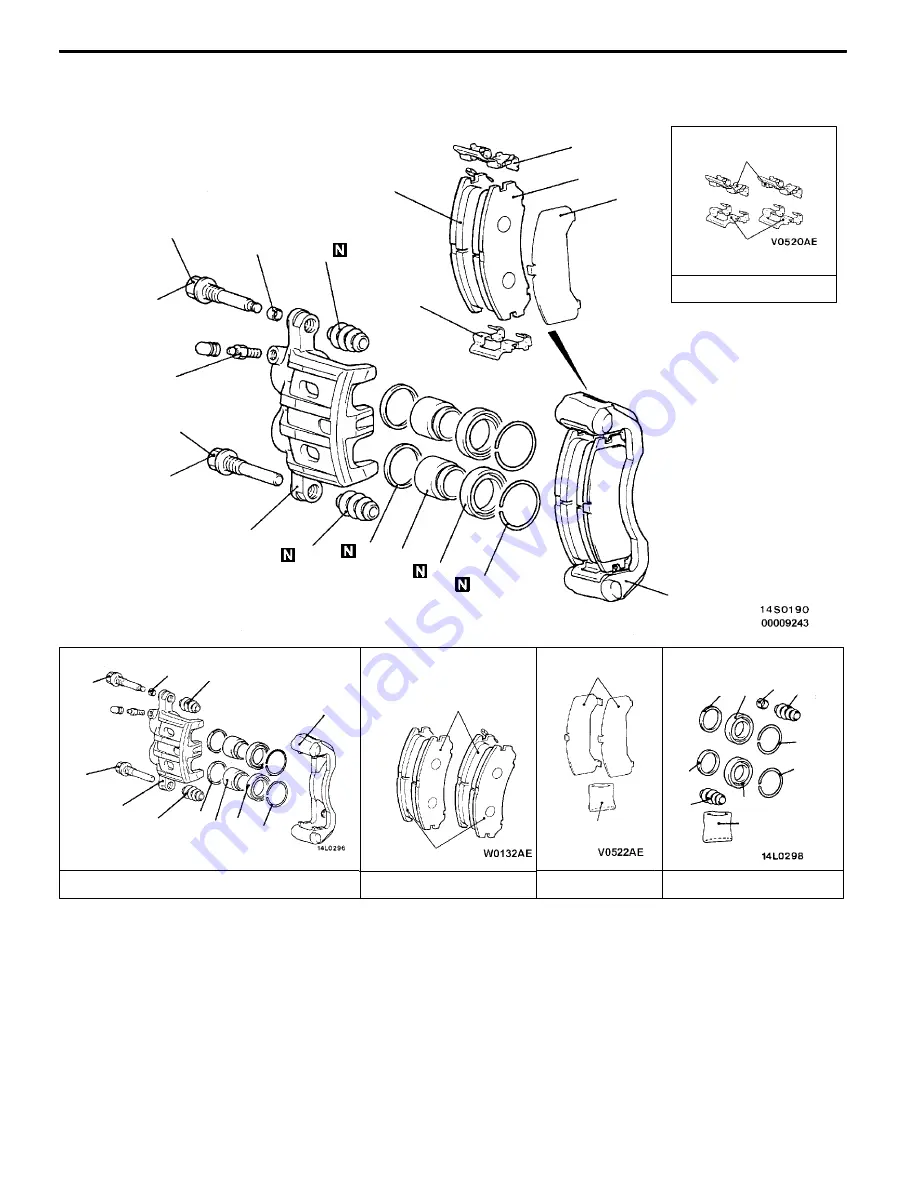
Mitsubishi MOTORS Space Runner 1998 Скачать руководство пользователя страница 682

BASIC BRAKE SYSTEM -

Disc Brake

35A-22

DISASSEMBLY AND REASSEMBLY

35100820044

10

11

12

13

14

1

2

3

4

5

6

7

8

9

74 Nm

8 Nm

74 Nm

Brake caliper kit

Pad set

Seal and boots kit

14

5

2

3

5

1

10

5

9

8 7 6

4

13

12

9

3 5

5

7

6

Grease

<FRONT>

Clip set

14

14

Shim set

6

7

9

Grease

11

Disassembly steps

"

A

A

1. Guide pin

"

A

A

2. Lock pin

3. Bushing

4. Caliper support (pad, clip, shim)

5. Pin boot

6. Boot ring

A

A

"

7. Piston boot

A

A

"

8. Piston

A

B

"

9. Piston seal

10. Caliper body

11. Pad and wear indicator assembly

12. Pad assembly

13. Outer shim

14. Clip

Содержание Space Runner 1998

Страница 1: ...ssembly inspection adjustment reassembly and installation Use the following manuals in combination with this manual as required TECHNICAL INFORMATION MANUAL PYDE9802 WORKSHOP MANUAL ENGINE GROUP PWEEj...

Страница 2: ...r bag module and seat belt with pre tensioner before drying or baking the vehicle after painting SRS ECU air bag module clock spring and side impact sensor 93_C or more Seat belt with pre tensioner 90...

Страница 3: ...nspection 11 Inspection Service Points for a Blown Fuse 12 Points to Note for Intermittent Malfunctions 12 VEHICLE IDENTIFICATION 13 Vehicle Information Code Plate 13 Models 13 Model Code 15 Chassis N...

Страница 4: ...servicing procedures visual inspections should always be performed as well DEFINITION OF TERMS STANDARD VALUE Indicates the value used as the standard for judging the quality of a part or assembly on...

Страница 5: ...pped with the 1 800 mL 4G93 petrol engine 2400 Indicates models equipped with the 2 400 mL 6G64 petrol engine GDI Indicates the gasoline direct injection M T Indicates the manual transmission or model...

Страница 6: ...of removal steps D Reassembly steps Specified in case reassembly is impossible in reverse order of disassembly steps Omitted if reassembly is possible inreverse order of disassembly steps Classificati...

Страница 7: ...is applied Indicates the section title Indicates the group num ber Indicates the page number Indicates the group title Denotes non reus able part Repair kit or set parts are shown Only very frequently...

Страница 8: ...mation from the customer Check trouble symptom Reoccurs Does not reoccur Read the diagnosis code No diagnosis code or communication with MUT II not possible Refer to the INSPECTION CHART FOR TROUBLE S...

Страница 9: ...ing to each trouble symptoms classified in the Inspection Chart for Trouble Symptoms Refer to P 00 9 for how to use the inspection procedures 8 SERVICE DATA REFERENCE TABLE Inspection items and normal...

Страница 10: ...code by warning lamp When the diagnosis code No 24 is output When no diagnosis code is output On Off 1 5 secs 0 5 sec 0 5 sec Pause time 3 secs Tens signal Place division 2 secs Units signal On Off 0...

Страница 11: ...at there are trouble symptoms If trouble symptoms have disappeared the connector may have been inserted incorrectly and the trouble symptom may have disappeared during inspection If it seems that trou...

Страница 12: ...e that if the connector control unit etc is too small to permit insertion of the test bar it should not be forced use a special tool the extra thin probe in the harness set for checking for this purpo...

Страница 13: ...d the terminal connections male and female pins will not be perfect even if the connector body is connected and the pins may pull out of the reverse side of the connector Therefore gently pull the har...

Страница 14: ...becomes simple In order to ascertain the conditions under which an intermittent malfunction occurs first ask the customer for details about the driving conditions weather conditions frequency of occu...

Страница 15: ...el series 2 ENGINE 4G64 Engine model 3 EXT A69A Exterior code 4 TRANS AXLE F5M42 Transmission code 5 COLOR A69 50H 03V A69 Body colour code INT OPT 50H Interior code 03V Equipment code For monotone co...

Страница 16: ...ngine model Transmission model Fuel supply system N84W LNUCL6 R6 4G64 DOHC GDI F5M42 GDI LNFCL6 2 351 mL 2WD 5M T LNUGL6 LNHCL6 R6 LNGCL6 LNHGL6 LRUCL6 R6 F4A42 LRFCL6 2WD 4A T LRUGL6 LRHCL6 R6 LRGCL6...

Страница 17: ...1 800 mL petrol engine 4 2 400 mL petrol engine 3 Body type W Wagon 4 Body style S 3 door station wagon L 4 door station wagon 5 Transmission type N 5 speed manual transmission R 4 speed automatic tr...

Страница 18: ...A For Europe right hand drive B For Europe left hand drive 4 Body style S 3 door station wagon L 4 door station wagon 5 Transmission type N 5 speed manual transmission R 4 speed automatic transmission...

Страница 19: ...570107 1 The engine model number is stamped at the cylinder block as shown in the following Engine model Engine displacement 4G93 4G64 1 834 2 351 2 The engine serial number is stamped near the engine...

Страница 20: ...rack front 5 1 460 1 460 Track rear 6 1 465 1 465 Overhang front 7 890 890 Overhang rear 8 850 850 Ground clear ance unladen 9 155 155 Vehicle Kerb weight 1 360 1 380 weight kg Max gross vehicle weigh...

Страница 21: ...5 1 535 1 535 1 535 1 535 1 535 Overhang front 7 890 890 890 890 890 890 Overhang rear 8 930 930 930 930 930 930 Ground clear ance unladen 9 155 155 155 155 155 155 Vehicle Kerb weight 1 510 1 510 1 5...

Страница 22: ...surface and placed so that the pad surface is facing upward Do not place anything on top of it 6 Never attempt to disassemble or repair the SRS components SRS air bag control unit air bag module cloc...

Страница 23: ...the oxygen sensor with a protective cover when applying anti corrosion agents and undercoats PRE INSPECTION CONDITION Pre inspection condition refers to the condition that the vehicle must be in befo...

Страница 24: ...ay be carried out which involve the electrical or fuel systems MUST be carried out in accordance with MMC s information Instructions ENGINE OILS Health Warning Prolonged and repeated contact with mine...

Страница 25: ...s a risk of eye contact eye protection should be worn for example chemical goggles or face shields in addition an eye wash facility should be provided D Obtain First Aid treatment immediately for open...

Страница 26: ...on the instrument panel indicates the operational status of the SRS The clock spring is installed in the steering column The SRS side air bag deploys if an impact received at the side of the vehicle...

Страница 27: ...nerator Rotor SRS ECU SRS SERVICE PRECAUTIONS 00100600073 1 In order to avoid injury to yourself or others from accidental deployment of the air bag and accidental operation of the seat belt with pre...

Страница 28: ...nstrument panel wiring harness Combination meter SRS warning lamp harness 5 6 Instrument panel wiring harness Air bag module Front passenger s side 7 8 Instrument panel wiring harness Clock spring Cor...

Страница 29: ...y MB991222 SRS ECU harness connector SRS ECU harness connector rear side 7 SRS components and seat belt with pre tensioner should not be subjected to heat so remove the SRS ECU air bag module driver s...

Страница 30: ...Caution Do not support the vehicles at locations other than specified supporting points If do so this will cause damage etc SUPPORT POSITIONS FOR A GARAGE JACK AND AXLE STANDS GARAGE JACK Caution Neve...

Страница 31: ...OST LIFT OR DOUBLE POST LIFT Caution When service procedures require removing rear suspension spare tyre and rear bumper place additional weight on rear end of vehicle or anchor vehicle to hoist to pr...

Страница 32: ...dure 1 Place the vehicle on the H bar lift same direction 2 Place attachments on the H bar lift at the designated chassis support positions When making the attachments refer to the section concerning...

Страница 33: ...e wood selected for the blocks must be hard 2 For the B blocks and C blocks use a saw and chisel or similar tool to make grooves of the dimensions shown in the figure 3 Make four ATTACHMENTS such as s...

Страница 34: ...ned to plastic or die cast inserted nuts 4 If self tapping screws or self locking nuts are used Standard bolt and nut tightening torque Thread size Torque Nm Bolt nominal diameter mm Pitch mm Head mar...

Страница 35: ...ENGINE 4G6 11A ENGINE 4G9 11B 11A 1 ENGINE CONTENTS 11109000276...

Страница 36: ...ion Check and Adjustment 6 Ignition Timing Check 10 Idle Speed Check 11 Idle Mixture Check 12 Compression Pressure Check 13 Manifold Vacuum Check 14 Lash Adjuster Check 14 CRANKSHAFT PULLEY 17 CAMSHAF...

Страница 37: ...ing ATDC 16_ Fuel system Electronically controlled multipoint fuel injection Rocker arm Roller type Auto lash adjuster Equipped SERVICE SPECIFICATIONS Items Standard value Limit Alternator drive Vibra...

Страница 38: ...ompression pressure kPa r min 1 570 300 1 210 300 Compression pressure difference of all cylinder kPa Max 100 Intake manifold vacuum kPa Min 56 3 Cylinder head bolt shank length mm 99 4 Auto tensioner...

Страница 39: ...990767 End yoke holder D Holding the camshaft sprocket D Holding the crankshaft sprocket MD998719 or MD998754 Crankshaft pulley holder pin D Holding the camshaft sprocket D Holding the crankshaft spro...

Страница 40: ...ing belt tension adjustment GENERAL SERVICE TOOL MZ203827 Engine lifter Supporting the engine assembly during removal and installation of the transmission MB991453 Engine hanger assembly ON VEHICLE SE...

Страница 41: ...re 2 Do not let any contaminants such as water or oil get onto the microphone 3 If strong gusts of wind blow against the microphone or if there are any loud sources of noise nearby the values measured...

Страница 42: ...ion to the standard values Standard value Items When a used belt is installed When a new belt is installed Vibration frequency Hz 201 222 241 276 Tension N 441 539 637 833 Deflection Reference value m...

Страница 43: ...for information regarding the vibration frequency measurement method using MUT II When measuring the tension Use a belt tension gauge to measure the belt tension When measuring the deflection Apply 9...

Страница 44: ...coil No 1 NOTE The power supply line is looped and also longer than the other ones 4 Start the engine and let it run at idle 5 Use the MUT II to measure engine idle speed and check that it is within t...

Страница 45: ...ately 5 degree 11 Remove the timing light 12 Turn off the ignition switch and then remove the MUT II IDLE SPEED CHECK 1 Before inspection set the vehicle to the pre inspection condition For vehicles w...

Страница 46: ...ition timing is within the standard value NOTE Refer to P 11A 10 concerning the check procedure of the basic ignition timing Standard value 5_ BTDC 3_ 4 Run the engine at 2 500 r min for 2 minutes 5 S...

Страница 47: ...ith the throttle valve fully open and measure the compression pressure Standard value at engine speed of 300 r min 1 570 kPa Limit at engine speed of 300 r min Min 1 210 kPa 7 Measure the compression...

Страница 48: ...e is a problem with the lash adjusters the noise will almost never disappear even if the engine has been run at idle to let it warm up The only case where the noise might disappear is if the oil in th...

Страница 49: ...into the high pressure chamber when starting the engine 2 After parking the vehicle for long periods the oil drains out of the oil passage and it takes time for the oil to be supplied to the lash adju...

Страница 50: ...2 Run the engine at idle for 1 3 minutes to let it warm up 3 With no load on the engine repeat the drive pattern shown in the illustration at left and check if the abnormal noise disappears The noise...

Страница 51: ...L AND INSTALLATION Pre removal Operation Under Cover Removal Post installation Operation D Drive Belt Tension Adjustment Refer to P 11A 6 D Under Cover Installation 1 2 3 25 Nm e Removal steps 1 Drive...

Страница 52: ...GROUP 13A D Intake Manifold Installation Refer to GROUP 15 D Timing Belt Installation Refer to P 11A 30 D Air Intake Hose Assembly Installation D Engine Coolant Supplying D Drive Belt Tension Adjustme...

Страница 53: ...rication points Seen from underneath beam camshaft cap Sealant 3M ATD Part No 8660 or equivalent Sealant MITSUBISHI GENUINE PART MD970389 or equivalent Engine oil Lip section Seen from above cylinder...

Страница 54: ...is a screw hole for the cam position sensing cylinder mounting bolt on the exhaust side camshaft BA BEAM CAMSHAFT CAP INSTALLATION 1 Place the camshaft dowel pin as shown in the illustration 2 Tighte...

Страница 55: ...llustration DA CAMSHAFT SPROCKET INSTALLATION Use the special tool to secure the camshaft sprocket in the same way as during removal and then tighten the bolt to the specified torque Tightening torque...

Страница 56: ...allation Refer to GROUP 15 f 4 1 mm Bolt hole Groove 6 22 Nm 9 Nm 6 2 1 Sealant MITSUBISHI GENUINE PART MD970389 or equivalent 4 39 Nm 3 5 44 Nm 9 Nm 9 Nm Removal steps 1 Drain plug AA 2 Drain plug ga...

Страница 57: ...E 4G6 Oil Pan 11A 23 INSTALLATION SERVICE POINT AA DRAIN PLUG GASKET INSTALLATION Install the drain plug gasket in the direction so that it faces as shown in the illustration Drain plug gasket Oil pan...

Страница 58: ...170 or equivalent Lip section Lip section Engine oil 127 137 Nm 6 9 4 3 M T Crankshaft front oil seal removal steps D Timing belt Refer to P 11A 30 1 Crankshaft sprocket B 2 Key CA 3 Crankshaft front...

Страница 59: ...ADAPTER PLATE FLYWHEEL M T DRIVE PLATE A T REMOVAL Use the special tool to secure the flywheel or drive plate and remove the bolts INSTALLATION SERVICE POINTS AA CRANKSHAFT REAR OIL SEAL INSTALLATION...

Страница 60: ...o the crankshaft thread holes 4 Apply sealant to the threaded mounting holes Specified sealant 3M Stud locking 4170 or equivalent 5 Use the special tool to hold the flywheel or drive plate in the same...

Страница 61: ...o GROUP 15 D Fuel Pressure Regulator High Pressure and Fuel Pump High Pressure Removal and Installation Refer to GROUP 13A D Thermostat Case Assembly Removal and Installation Refer to GROUP 14 Water H...

Страница 62: ...rom the gasket mounting surface 2 Install so that the shapes of the cylinder head holes match the shapes of the respective cylinder head gasket holes BA CYLINDER HEAD BOLT INSTALLATION 1 When installi...

Страница 63: ...order shown in the illustration Mark the head of the cylinder head bolt and cylinder head by paint 5 Tighten 90_ of a turn In the order shown in the illustration Check that the painted mark of the hea...

Страница 64: ...e Mount Bracket Removal and Installation Refer to GROUP 32 Engine Mounting 10 12 Nm 48 Nm 1 2 5 22 Nm 4 6 9 Nm 24 Nm 10 12 Nm 9 Nm 3 9 Nm 108 127 Nm 19 Nm 10 11 9 8 7 Removal steps 1 Water pump pulley...

Страница 65: ...nsion pulley centre bolt 3 Move the tension pulley to the water pump side and then remove the timing belt Caution If the timing belt is to be re used use chalk to mark on its flat side an arrow indica...

Страница 66: ...lding the timing belt B tensioner up with your finger in the direction of the arrow place pressure on the timing belt so that the tension side of the belt is taut Now tighten the bolt to fix the tensi...

Страница 67: ...andard value Within 1 mm A Length when it is free not pressed B Length when it is pressed A B Movement 2 If it is out of the standard value replace the auto tensioner 3 Use a press or vice to gently c...

Страница 68: ...goes in 60 mm or more The screwdriver should not be taken out until the timing belt is installed 3 Install the timing belt by the following procedure Take care not to slacken the belt at the tension...

Страница 69: ...t are at the bottom press the tension pulley lightly against the timing belt and then provisionally tighten the centre bolt 5 Check to be sure that all timing marks are aligned 6 Adjust the timing bel...

Страница 70: ...ming marks are aligned After leaving it for 15 minutes measure the amount of protrusion of the auto tensioner Standard value A 3 8 4 5 mm 4 If the amount of protrusion is outside the standard value re...

Страница 71: ...On vehicle Service D Hood Removal and Installation Refer to GROUP 42 D Transmission Assembly Removal and Installation Refer to GROUP 22 or 23 D Drive Belt Tension Adjustment Refer to P 11A 6 Post inst...

Страница 72: ...ance when removing and installing the engine assembly and tie it with a cord AC ENGINE MOUNT BRACKET REMOVAL 1 Support the engine with a garage jack 2 Remove the special tool which was attached when t...

Страница 73: ...stopper so that the arrow points in the direction as shown in the diagram CA ENGINE MOUNT BRACKET INSTALLATION 1 Place a garage jack against the engine oil pan with a piece of wood in between and inst...

Страница 74: ...NOTES...

Страница 75: ...Belt Tension Check and Adjustment 6 Ignition Timing Check 9 Idle Speed Check 10 Idle Mixture Check 11 Compression Pressure Check 12 Manifold Vacuum Check 13 Lash Adjuster Check 13 CRANKSHAFT PULLEY 16...

Страница 76: ...ATDC 15_ Fuel system Electronically controlled multipoint fuel injection Rocker arm Roller type Auto lash adjuster Equipped SERVICE SPECIFICATIONS Items Standard value Limit Alternator drive Vibration...

Страница 77: ...led 7 0 9 0 Basic ignition timing 5_ BTDC 3_ Ignition timing Approx 16_BTDC Approx 6_BTDC 2 Idle speed r min M T 600 100 1 750 100 2 A T 650 100 750 100 2 CO contents 0 5 or less HC contents ppm 100 o...

Страница 78: ...ber Name Use MB991502 MUT II sub assembly D Measuring the drive belt tension D Checking the ignition timing D Checking the idle speed D Erasing diagnosis code MB991668 Belt tension meter set Measuring...

Страница 79: ...al MB990938 Handle MD998717 Crankshaft front oil seal installer Press in of the crankshaft front oil seal MD998767 Tension pulley socket wrench Timing belt tension adjustment GENERAL SERVICE TOOL MZ20...

Страница 80: ...shown in the illustration and check that the vibration frequency of the belt is within the standard value Caution 1 The temperature of the surface of the belt should be as close as possible to normal...

Страница 81: ...t 3 Use the adjusting bolt to adjust the belt tension and belt deflection to the standard values Standard value Items When a used belt is installed When a new belt is installed Vibration frequency Hz...

Страница 82: ...for information regarding the vibration frequency measurement method using MUT II When measuring the tension Use a belt tension gauge to measure the belt tension When measuring the deflection Apply 98...

Страница 83: ...let it run at idle 5 Use the MUT II to measure engine idle speed and check that it is within the standard value Standard value Items Idle speed r min M T 600 100 750 100 A T 650 100 750 100 NOTE Indi...

Страница 84: ...oil temperature is more than 50 C NOTE The idle speed in vehicles with manual transmission varies as shown in the illustration in accordance with the transmission oil temperature 2 Turn off the igniti...

Страница 85: ...2 500 r min for 2 minutes 5 Set the CO HC tester 6 Check the CO contents and the HC contents at idle NOTE This measurement should be performed in less than approximately 4 minutes since the engine sp...

Страница 86: ...ith the throttle valve fully open and measure the compression pressure Standard value at engine speed of 300 r min 1 790 kPa Limit at engine speed of 300 r min Min 1 400 kPa 7 Measure the compression...

Страница 87: ...a problem with the lash adjusters the noise will almost never disappear even if the engine has been run at idle to let it warm up The only case where the noise might disappear is if the oil in the eng...

Страница 88: ...high pressure chamber when starting the engine 2 After parking the vehicle for long periods the oil drains out of the oil passage and it takes time for the oil to be supplied to the lash adjuster so a...

Страница 89: ...2 Run the engine at idle for 1 3 minutes to let it warm up 3 With no load on the engine repeat the drive pattern shown in the illustration at left and check if the abnormal noise disappears The noise...

Страница 90: ...1 2 3 4 177 186 Nm 5 Removal steps 1 Drive belt Power steering and A C 2 Drive belt Alternator AA AA 3 Crankshaft pulley bolt 4 Crankshaft pulley washer 5 Crankshaft pulley REMOVAL SERVICE POINT AA C...

Страница 91: ...ressure 1 2 3 4 5 6 7 8 9 10 11 12 13 14 15 Apply engine oil to all sliding parts during installation 3 4 Nm 21 25 Nm 12 15 Nm 22 Nm 10 12 Nm 21 25 Nm 10 12 Nm 10 12 Nm 35 Nm 88 Nm Removal steps 1 Con...

Страница 92: ...rication points Seen from underneath beam camshaft cap Sealant 3M ATD Part No 8660 or equivalent Sealant MITSUBISHI GENUINE PART MD970389 or equivalent Engine oil Lip section Seen from above cylinder...

Страница 93: ...sition sensing cylinder mounting bolt on the exhaust side camshaft BA BEAM CAMSHAFT CAP INSTALLATION 1 Place the camshaft dowel pin as shown in the illustration 2 Tighten the beam camshaft cap mountin...

Страница 94: ...the entire circumference of the oil seal lip 2 Press fit the oil seal as shown in the illustration DA CAMSHAFT SPROCKET INSTALLATION Use the special tool to secure the camshaft sprocket in the same w...

Страница 95: ...pe Removal and Installation Refer to GROUP 15 D Engine Oil Draining and Supplying Refer to GROUP 12 On vehicle Service Groove Bolt hole Sealant MITSUBISHI GENUINE PART MD970389 or equivalent 1 2 3 4 5...

Страница 96: ...ould not be used AB UPPER OIL PAN REMOVAL Insert a flat tipped screwdriver into the notch of the upper oil pan as shown in the illustration and turn it to remove the oil pan Caution Because the upper...

Страница 97: ...hole Lip Lip M T A T Crankshaft front oil sealremoval steps D Timing belt Refer to P 11B 28 D Crank angle sensor Refer to GROUP 16 1 Crankshaft sprocket 2 Key 3 Crankshaft sensing blade 4 Crankshaft...

Страница 98: ...n off all sealant oil and other substances which are adhering to the threaded bolts crankshaft thread holes and the flywheel or drive plate 2 Apply oil to the bearing surface of the flywheel or drive...

Страница 99: ...cle Service D Timing Belt Removal and Installation Refer to P 11B 28 D Intake Manifold Removal and Installation Refer to GROUP 15 D Fuel Pump High pressure and Fuel Pressure Regulator High pressure Re...

Страница 100: ...ssembly from the engine with the hose attached NOTE Place the removed power steering oil pump and bracket assembly in a place where it will not be a hindrance when removing and installing the cylinder...

Страница 101: ...oosen Carry out in the reverse order of that shown in the illustration 3 Tighten to 20 Nm Carry out in the order shown in the illustration 4 Tighten 90_ of a turn In the order shown in the illustratio...

Страница 102: ...on Refer to P 11B 16 20 25 Nm 9 Nm 10 12 Nm 49 Nm 9 Nm 49 Nm 12 15 Nm 35 Nm 1 2 3 4 5 6 7 8 9 10 Removal steps 1 Alternator brace 2 Timing belt front upper cover 3 Power steering pump bracket stay 4 T...

Страница 103: ...movement of the push rod Standard value Within 1 mm A Length when it is free not pressed B Length when it is pressed A B Movement 2 If it is out of the standard value change the auto tensioner 3 Use a...

Страница 104: ...ise direction 4 Place the timing belt on the exhaust side camshaft sprocket and hold it in the position shown in the illustration with a paper clip 5 Place the timing belt on the intake side sprocket...

Страница 105: ...ng the special tool and a torque wrench apply tension to the timing belt then tighten the fixing bolt at the specified torque Standard Value 2 5 4 0 Nm timing belt tension torque reference value Cauti...

Страница 106: ...rted then it is satisfactory if the amount of protrusion of the auto tensioner rod is within the standard value Standard value A 3 8 4 5 mm If it is outside the standard value repeat the operations in...

Страница 107: ...al and Installation Refer to GROUP 42 D Drive Belt Tension adjustment after installation only Refer to P 11B 6 Engine oil 8 8 Nm 1 2 3 4 5 6 7 8 9 10 11 12 13 10 O ring Removal steps 1 Ignition coil c...

Страница 108: ...r hose connection 17 Oxygen sensor connector 18 Alternator connector 19 Engine oil pressure switch connector 20 Drive belt Power steering and A C 21 Power steering oil pump bracket stay AA 22 Power st...

Страница 109: ...hindrance when removing and installing the engine assembly and tie it with a cord AC ENGINE MOUNT BRACKET REMOVAL 1 Support the engine with a garage jack 2 Remove the special tool which was attached w...

Страница 110: ...in block and support the engine assembly with the special tool CA HIGH PRESSURE FUEL HOSE INSTALLATION 1 Apply a small amount of new engine oil to the O ring Caution Do not let any engine oil get into...

Страница 111: ...S GENERAL INFORMATION 2 SERVICE SPECIFICATIONS 3 SEALANT 3 LUBRICANTS 3 SPECIAL TOOLS 3 ON VEHICLE SERVICE 4 Engine Oil Check 4 Engine Oil Replacement 4 Oil Filter Replacement 5 Oil Level Warning Syst...

Страница 112: ...reasing components where practicable before handling them Other precautions D Avoid prolonged and repeated contact with oils particularly used engine oils D Wear protective clothing including impervio...

Страница 113: ...ark Oil pressure switch 3M ATD Part No 8660 or equivalent LUBRICANTS Items Specifications Engine oil API classification SG or higher Engine oil quantity L Oil filter 0 3 Total 3 8 SPECIAL TOOLS Tool N...

Страница 114: ...Remove the engine oil filler cap 3 Remove the drain plug to drain oil Caution Use care as oil could be hot 4 Install a new drain plug gasket so that it faces in the direction shown in the illustratio...

Страница 115: ...of engine oil to the O ring of the new oil filter 8 Once the O ring of the oil filter is touching the flange use the respective tool in the following table to tighten to the specified torque 9 Install...

Страница 116: ...ctor is the same as the battery voltage the problem is probably a malfunction of either the oil level relay or the oil level sensor 2 If the voltage at the connector is lower than the battery voltage...

Страница 117: ...age the oil pressure switch when removing it 4 Install the oil pressure gauge NOTE Use a adapter of PT 1 8 thread 5 Run the engine to warm it 6 After the engine has been warmed up check that oil press...

Страница 118: ...the special tool to tighten the oil pressure switch to the specified torque Tightening torque 19 Nm Caution Do not start the engine within one hour after the oil pressure switch has been installed 10...

Страница 119: ...13A 1 FUEL CONTENTS GASOLINE DIRECT INJECTION GDI 4G6 13A GASOLINE DIRECT INJECTION GDI 4G9 13B FUEL SUPPLY 13C...

Страница 120: ...trol Relay Fuel Pump Relay Injector Driver Control Relay and Throttle Valve Control Servo Relay Continuity Check 106 Intake Air Temperature Sensor Check 106 Engine Coolant Temperature Sensor Check 106...

Страница 121: ...s the air fuel ratio at a richer than usual level to maintain driveability When the engine is under low or medium loads the air fuel ratio becomes leaner to reduce fuel consumption When the engine is...

Страница 122: ...FUNCTIONS 1 Fuel Pump Control Turns the fuel pump relay ON so that current is supplied to the fuel pump while the engine is cranking or running 2 A C Relay Control Turns the compressor clutch of the A...

Страница 123: ...on sensor Hall element type Crank angle sensor Hall element type Detonation sensor Piezoelectric type Fuel pressure sensor Metallic membrane type Power steering fluid pressure switch Contact switch ty...

Страница 124: ...Power supply D Ignition switch IG D Accelerator pedal posi tion sensor 2 D Engine ECU Engine ECU From fuel pump low pressure To fuel tank 10 Fuel pressure sensor 5 Camshaft position sensor 4 Throttle...

Страница 125: ...position sensor kW 3 5 6 5 Intake air temperature sensor at 20_C 2 3 3 0 resistance kW at 80_C 0 30 0 42 Engine coolant temperature at 20_C 2 1 2 7 sensor resistance kW at 80_C 0 26 0 36 Fuel pressure...

Страница 126: ...ection D Commercial tester connection MB991502 MUT II sub assembly D Reading diagnosis code D GDI system inspection MB991348 MB991658 Test harness set D Measurement of voltage during trouble shooting...

Страница 127: ...leshooting Inspection Service Points NOTE If the engine ECU is replaced the steering lock cylinder and ignition key should be replaced together with it DIAGNOSIS FUNCTION ENGINE WARNING LAMP CHECK ENG...

Страница 128: ...nd channel Electronic controlled throttle valve system Throttle valve control servo Throttle valve controller METHOD OF READING AND ERASING DIAGNOSIS CODES Refer to GROUP 00 How to Use Troubleshooting...

Страница 129: ...efective Engine coolant temperature sensor Controls as if the engine coolant temperature is 80_C Note that this control will continue until the ignition switch is turned off even if the sensor signal...

Страница 130: ...electronic controlled throttle valve system 2 Disables lean mixture combustion 3 Disables idle engine speed feedback control Throttle valve position feedback 1 Disables the electronic controlled throt...

Страница 131: ...e system 13A 28 59 Oxygen sensor rear system 13A 30 61 Communication line with A T ECU system 13A 31 64 Alternator FR terminal system 13A 31 66 Brake vacuum sensor system 13A 32 77 Accelerator pedal p...

Страница 132: ...asure at the oxygen sensor front connector B 17 D Disconnect the connector and measure at the harness side 1 Voltage between 2 and earth Ignition switch ON OK System voltage 2 Continuity between 4 and...

Страница 133: ...h ON OK 6 9 V NG Check the following connector A 07 OK Check trouble symptom OK Check the following connector A 07 NG Check the harness wire between the engine ECU and the air flow sensor and repair i...

Страница 134: ...ure sensor circuit D Malfunction of the engine ECU NG Repair NG Repair OK Replace the engine ECU NG Repair NG OK Check trouble symptom OK Check the following connector A 07 NG Check the harness wire b...

Страница 135: ...NG Replace OK Measure at throttle position sensor con nector A 73 D Disconnect the connector and measure at the harness side D Voltage 1 and earth Ignition switch ON OK 4 8 5 2 V D Continuity between...

Страница 136: ...5 minutes or more have passed since the engine coolant temperature after filtering has dropped from 40_C or more to less than this temperature NG Repair NG Repair OK Replace the engine ECU NG Repair...

Страница 137: ...Check the harness wire between the engine ECU and the crank angle sen sor OK Check trouble symptom 2 NG Check the following connector B 51 OK Check the following connector A 71 Measure at the crank an...

Страница 138: ...ition sensor OK Check trouble symptom OK Check the following connector A 78 NG Check the harness wire between the engine ECU and the camshaft position sensor OK Check trouble symptom 2 NG Check the fo...

Страница 139: ...ort circuited harness wire of the vehicle speed sensor circuit D Malfunction of the engine ECU Does the speedometer operate normally No Check the vehicle speed sensor circuit Refer to GROUP 54 Combina...

Страница 140: ...onnector D Voltage between 85 and earth Ignition switch ON OK 3 9 4 1 V at altitude of 0 m 3 3 3 6 V at altitude of 1 200 m NG Check the harness wire between the engine ECU and the barometric pres sur...

Страница 141: ...ircuit or short circuited harness wire of the detonation sensor D Malfunction of the engine ECU NG Repair NG Replace the engine ECU NG Check the harness wire between the detonation sensor and the eart...

Страница 142: ...Check the following connectors B 28 B 89 B 103 OK Check trouble symptom NG Check the harness wire between the injector driver relay and ignition switch and repair if necessary NG Repair NG Check the h...

Страница 143: ...minal 2 and earth Voltage between terminal 14 and earth Voltage between terminal 15 and earth Ignition switch ON OK 8 11 V OK Check the following connectors B 52 B 54 NG Repair OK Check trouble sympto...

Страница 144: ...nto the air intake system D Damaged intake manifold gasket D Damaged vacuum hose D Damaged air intake hose D Check the EGR valve OK Check the injector system Refer to P 13A 24 INSPECTION PRO CEDURE FO...

Страница 145: ...e engine radio interference may cause this code to be displayed 2 This code may be displayed when registering the key encrypted code NG Repair No Is there another ignition key near the ignition key th...

Страница 146: ...engine run at 2 000 r min for at least fifteen seconds After the air bleeding the diagnosis code must be erased by the MUT II D Air sucking due to no fuel supply OK MUT II Data list 74 Fuel pressure s...

Страница 147: ...between the engine ECU and the fuel pressure sen sor OK Check trouble symptom NG Check the harness wire between the engine ECU and the fuel pressure sen sor OK Check trouble symptom OK Check the follo...

Страница 148: ...tion of the engine ECU Check the oxygen sensor rear Refer to P 13A 109 NG Replace OK Measure at the oxygen sensor rear connector C 29 D Disconnect the connector and measure at the harness side 1 Volta...

Страница 149: ...voltage from the alternator FR terminal is system voltage for 20 seconds D Open circuit in alternator FR terminal circuit D Malfunction of the engine ECU NG Repair NG Repair OK Replace the engine ECU...

Страница 150: ...engine ECU and the brake vacuum sen sor OK NG Check the harness wire between the engine ECU and the brake vacuum sen sor OK Check trouble symptom NG Check the harness wire between the engine ECU and t...

Страница 151: ...P 13A 108 Check the accelerator pedal position sensor 2nd channel Refer to P 13A 108 NG Replace the accelerator pedal position sensor assembly 2nd channel OK Measure at accelerator pedal position sen...

Страница 152: ...1st channel Refer to P 13A 98 NG Repair OK Replace the engine ECU MUT II Data list 26 Accelerator pedal position switch P 13A 77 NG Check the accelerator pedal position switch system Refer to P 13A 67...

Страница 153: ...he harness side D Voltage between terminal 1 and earth Ignition switch ON OK 4 8 5 2 V D Continuity between terminal 3 and earth OK Continuity NG Check the following connector B 50 NG Repair OK Check...

Страница 154: ...13A 75 NG Check the air flow sensor system Refer to P 13A 15 INSPECTION PROCEDURE FOR DIAGNOSIS CODE No 12 OK Replace the fuel pump high pressure Code No 91 Electronic controlled throttle valve system...

Страница 155: ...to P 13A 111 NG Replace OK Check the following connectors A 99 B 50 NG Repair OK Check trouble symptom NG Check the harness wire between the throttle control servo and throttle valve controller NG Re...

Страница 156: ...the throttle valve control servo and throttle valve controller OK Replace the throttle valve controller NG Repair Code No 99 Malfunction in throttle valve control servo motor system 2nd phase Probabl...

Страница 157: ...g Rough idling hunting 7 13A 48 Improper idling Idling speed is high Improper idling speed 8 13A 50 Idling speed is low Improper idling speed Idling stability When the engine is cold it stalls at idli...

Страница 158: ...the accelerator pedal regardless of whether the vehicles is moving or not Engine stall Pass out The engine stalls when the accelerator pedal is depressed or while it is being used Driving Hesitation...

Страница 159: ...n with MUT II is not possible Communication with all systems is not possible Probable cause The cause is probably a defect in the power supply system including earth for the diagnosis line D Malfuncti...

Страница 160: ...cuit D Malfunction of engine ECU D Open circuit between the engine ECU and diagnosis connector NG Check the harness wire between engine ECU and diagnosis con nector NG Repair OK Check trouble symptom...

Страница 161: ...Replace OK Measure at the combination meter connector B 01 D Disconnect the connector and measure at the harness side D Voltage between 42 and earth Ignition switch ON OK System voltage NG Check the e...

Страница 162: ...Check the crank angle sensor system Refer to P 13A 19 INSPEC TION PROCEDURE FOR DIAGNOSIS CODE 22 OK MUT II Data list 21 Engine coolant temperature sensor Refer to P 13A 76 NG Check the engine coolan...

Страница 163: ...aution Never touch the connector terminal as approx 100 V is applied to the injector or you are seriously injured 4 Earth the spark plug electrode securely 5 Check that the spark plug ignites when the...

Страница 164: ...temperature sensor Refer to P 13A 76 NG Check the engine coolant temperature system Refer to P 13A 18 INSPECTION PROCEDURE FOR DIAGNOSIS CODE 21 OK MUT II Data list 18 Cranking signal Refer to P 13A...

Страница 165: ...aution Never touch the connector terminal as approx 100 V is applied to the injector or you are seriously injured 4 Earth the spark plug electrode securely 5 Check that the spark plug ignites when the...

Страница 166: ...tion feedback system Refer to P 13A 37 INSPECTION PROCEDURE FOR DIAGNOSIS CODE 92 OK MUT II Data list 26 Accelerator pedal position switch Refer to P 13A 77 NG Check the accelerator pedal position swi...

Страница 167: ...sensor and timing belt cover are properly installed OK Check ignition coil spark for each cylinder 1 Remove the ignition coil 2 Install a new spark plug to the removed ignition coil 3 Disconnect the i...

Страница 168: ...ition switch Refer to P 13A 77 NG Check the accelerator pedal position switch system Refer to P 13A 67 INSPECTION PROCEDURE 27 OK MUT II Data list 21 Engine coolant temperature sensor Refer to P 13A 7...

Страница 169: ...TION PROCEDURE 27 OK MUT II Data list 21 Engine coolant temperature sensor Refer to P 13A 76 NG Check the engine coolant temperature sensor Refer to P 13A 18 INSPECTION PROCEDURE FOR DIAGNOSIS CODE 21...

Страница 170: ...ry ignition signal D Power supply to the engine ECU Yes MUT II Data list 26 Accelerator pedal position switch Refer to P 13A 77 NG Check the accelerator pedal position switch Refer to P 13A 67 INSPECT...

Страница 171: ...s Clean around the throttle valve Refer to P 13A 97 No NG Check that the crank angle sensor and timing belt cover are properly installed OK Check ignition coil spark for each cylinder 1 Remove the ign...

Страница 172: ...DURE 29 OK MUT II Actuator test 08 Purge control solenoid valve Refer to P 13A 81 NG Check the purge control solenoid valve system Refer to P 13A 70 INSPECTION PROCEDURE 30 OK Check ignition coil spar...

Страница 173: ...pedal position switch Refer to P 13A 67 INSPECTION PROCEDURE 27 OK MUT II Data list 79 Throttle position sensor 1st channel Refer to P 13A 80 NG Check the throttle valve position feedback system Refe...

Страница 174: ...erature sensor Refer to P 13A 18 INSPECTION PROCEDURE FOR DIAGNOSIS CODE 21 OK MUT II Data list 79 Throttle position sensor 1st channel Refer to P 13A 80 NG Check the throttle valve position feedback...

Страница 175: ...n accelerating Probable cause The cause is probably an ignition leak being generated in line with an increase in the spark plug request voltage during acceleration D Malfunction of the ignition system...

Страница 176: ...ound the throttle valve Refer to P 13A 97 INSPECTION PROCEDURE 16 Knocking Probable cause The cause is probably incorrect detonation control or improper heat range of the spark plugs D Malfunction of...

Страница 177: ...P 13A 14 IN SPECTION PROCEDURE FOR DIAGNOSIS CODE 11 OK MUT II Data list 11 Oxygen sensor front OK 0 400 mV and 600 1 000 mV alternates when the engine is idling wait for four minutes after the engin...

Страница 178: ...system Refer to P 13A 69 INSPECTION PROCEDURE 29 OK MUT II Actuator test 08 Purge control solenoid valve Refer to P 13A 81 NG Check purge control solenoid valve system Refer to P 13A 70 INSPECTION PR...

Страница 179: ...harness wire between the alternator and the engine ECU and repair if necessary INSPECTION PROCEDURE 20 Idling speed is improper when A C is operating Probable cause If the engine ECU detects that the...

Страница 180: ...tor B 54 D Disconnect the connector measure at the harness side D Voltage between terminal 21 and earth Ignition switch ON OK 4 8 5 2 V The fan runs at high speed D Earth terminal 21 Ignition switch O...

Страница 181: ...U NG Repair NG Repair OK Replace the engine ECU 2 NG OK Check the trouble symptoms NG Replace the engine ECU OK Check the following connector B 67 Check the harness wire between the clutch switch conn...

Страница 182: ...ymptoms NG Check the harness wire between the engine ECU and the battery and repair if necessary NG Repair NG Replace the engine ECU OK Check the trouble symptoms OK Check the following connectors B 5...

Страница 183: ...onnector A 28 NG Repair Check the engine control relay Refer to P 13A 106 NG Replace INSPECTION PROCEDURE 25 Ignition switch ST system M T Probable cause The ignition switch ST outputs a HIGH signal t...

Страница 184: ...thestarter S terminal and repair if necessary 3 NG NG Repair OK Check the ignition switch Refer to GROUP 54 NG Repair NG Repair OK Replace the engine ECU NG Check the harness wire between the engine E...

Страница 185: ...Malfunction of the engine ECU NG Repair NG Repair Check the accelerator pedal position switch Refer to P 13A 109 NG Replace the accelerator pedal position sensor assembly OK Measure at accelerator pe...

Страница 186: ...3 4 and earth Ignition switch ON OK System voltage NG Check the following connectors B 28 B 89 B 103 NG Repair OK Check trouble symptom NG Check the harness wire between the fuel pump relay and igniti...

Страница 187: ...toms NG Check the harness wire between the engine ECU and EGR valve and repair if necessary OK Check the trouble symptoms NG Replace the engine ECU OK Check the following connector B 53 NG Repair OK M...

Страница 188: ...ecessary OK Check the trouble symptoms NG Replace the engine ECU OK Check the following connector B 54 NG Repair OK Measure at the engine ECU connector B 54 D Disconnect the connector and measure at t...

Страница 189: ...trouble symptom Check the harness wire between the engine ECU and power steer ing fluid pressure switch NG Repair OK OK Check the following connector A 96 Check trouble symptom NG INSPECTION PROCEDURE...

Страница 190: ...emperature sensor circuit D Malfunction of the engine ECU NG Repair Check the M T oil temperature sensor Refer to GROUP 22 On vehicle Service NG Replace OK Measure at the M T oil temperature sensor co...

Страница 191: ...nd measure at the harness side D Voltage between terminal 2 and earth OK System voltage NG Check the following connectors B 65 B 66 OK Check trouble symptom Check the harness wire between the battery...

Страница 192: ...ed D Improper connector contact open circuit or short circuited harness wire in the taillamp circuit D Malfunction of the engine ECU NG Replace the engine ECU OK Check the trouble symptoms OK Check th...

Страница 193: ...d the throttle valve has opened the accelerator pedal position switch and the accelerator pedal position sensor 1st channel need to be adjusted Item No Check items Requirements Normal condition Inspec...

Страница 194: ...FF Procedure No 25 M T 13A 65 M T 13A 66 switch ST Engine Cranking ON M T Procedure No 26 A T 13A 66 A T 21 Engine coolant temperature sensor Ignition switch ON Engine coolant temperature 20_C 20_C Co...

Страница 195: ...OFF Procedure No 32 13A 71 A C compressor is running when the A C switch is on A C switch ON ON No 32 29 Inhibitor switch Ignition switch ON Selector lever P or N P N Procedure No 26 13A 66 Selector...

Страница 196: ...ore Gradually increases to 50 90_C Procedure No 33 13A 72 49 A C relay Engine After warm up idling A C switch OFF OFF compressor clutch is not oper ating Procedure No 32 13A 71 A C switch ON ON compre...

Страница 197: ...ories OFF D Transmission Neutral A T P range Engine Idling 4 7 5 MPa 77 Accelerator pedal position Ignition switch ON Release the accel erator pedal 300 1 000 mV Code No 77 13A 33 sensor 2nd channel D...

Страница 198: ...itch ON Engine stopped Depress the accel erator pedal gradu ally Increases in re sponse to pedal depression stroke 4 600 5 200 mV 3 900 4 900 mV Engine After warm No load 450 1 000 mV up idling A C sw...

Страница 199: ...n t affect idling 07 Fuel pump low pressure Fuel pump operates and fuel is recirculated Ignition switch ON Sound of opera tion is heard Procedure No 28 13A 68 08 Purge control solenoid valve Solenoid...

Страница 200: ...empera ture 80 95_C D Ignition switch ON Engine Start the engine and then increase engine speed up to 3 500 r min Voltage decreases 6 Oxygen sensor heater Engine idling 0 3 V Engine 3 500 r min System...

Страница 201: ...operating D Headlamp OFF ON D Stop lamp OFF ON D Rear defogger switch OFF ON Voltage increases by 0 2 3 5 V 41 Alternator FR terminal D Engine Warm up and then idling D Radiator fan not operating D He...

Страница 202: ...52 Small lamp switch Lighting switch OFF 0 3 V Lighting switch ON Taillamp ON System voltage 57 Accelerator pedal position switch Ignition switch ON Release the accelerator pedal 0 1 V Depress the ac...

Страница 203: ...C 3 2 3 8 V Engine coolant temperature 20_C 2 3 2 9 V Engine coolant temperature 40_C 1 3 1 9 V Engine coolant temperature 80_C 0 3 0 9 V 84 Throttle position sensor 2nd channel Ignition switch ON Rel...

Страница 204: ...ing to the check chart NOTE 1 When measuring resistance and checking continuity a harness for checking contact pin pressure should be used instead of inserting a test probe 2 Checking need not be carr...

Страница 205: ...continuity when the accelerator pedal is slightly depressed 72 53 Intake air temperature sensor 5 3 6 7 kW when intake air temperature is 0_C 2 3 3 0 kW when intake air temperature is 20_C 1 0 1 5 kW...

Страница 206: ...pedal Fully closed Decreases slightly approx 2 V from system voltage 15 Throttle valve control servo B fully opened 2 Power supply to throttle valve control servo Ignition switch ON System voltage 5 P...

Страница 207: ...yzer special patterns pickup to engine ECU terminal 90 Standard Wave Pattern Observation conditions Function Special patterns Pattern height Low Pattern selector Display Engine r min Idle speed Standa...

Страница 208: ...ss MB991709 in between All terminals should be connected 2 Connect the analyzer special patterns pickup to camshaft position sensor terminal 2 3 Disconnect the crank angle sensor connector and connect...

Страница 209: ...o 1 TDC No 3 TDC No 4 TDC No 2 TDC Time 0 159 44 Wave Pattern Observation Points Check that cycle time T becomes shorter when the engine speed increases Examples of Abnormal Wave Patterns D Example 1...

Страница 210: ...Wave Pattern Observation conditions Function Special pattern Pattern height Low Pattern selector Display Engine r min Idle speed Standard wave pattern 4 0 8 4 0 V Injector open circuit check signal In...

Страница 211: ...cial patterns pickup to engine ECU terminal 10 No 1 ignition coil terminal 11 No 2 ignition coil terminal 23 No 2 ignition coil terminal 24 No 4 ignition coil respectively Standard Wave Pattern Observ...

Страница 212: ...y circuit Rectangular wave at power voltage Power transistor malfunction Examples of Abnormal Wave Patterns D Example 1 Wave pattern during engine cranking Cause of problem Open circuit in ignition pr...

Страница 213: ...1 and connection terminal 32 respectively Standard Wave Pattern Observation conditions Function Special patterns Pattern height High Pattern selector Display Engine condition When the engine coolant t...

Страница 214: ...attern Probable cause Coil reverse electromotive force does not appear or is extremely small Short in the coil Examples of Abnormal Wave Pattern D Example 1 Cause of problem Motor is malfunctioning Mo...

Страница 215: ...le for approx one minute 5 If carbon deposits are not removed from the throttle vale area repeat steps 3 and 4 6 Install the air intake hose 7 Use the MUT II or disconnect the negative battery cable f...

Страница 216: ...the battery cable is disconnected at step 11 let the engine run at idle for approx ten minutes ACCELERATOR PEDAL POSITION SWITCH AND ACCELERATOR PEDAL POSITION SENSOR ADJUSTMENT Caution 1 Never attem...

Страница 217: ...annel check that the output voltage of the accelerator pedal position sensor 2nd channel is identical to that of the sensor 1st channel 10 Loosen the mounting bolts of the accelerator pedal position s...

Страница 218: ...tting a suitable O ring or gasket between them 2 Install the special tool which was set up in step 1 between the high pressure fuel hose and the fuel pump high pressure 5 Connect the MUT II to the dia...

Страница 219: ...below Symptom Probable cause Remedy Fuel pressure drops gradually after engine is stopped Leaky fuel pressure regulator low pressure valve seat Replace fuel pressure regulator low pressure Fuel press...

Страница 220: ...y to be a leak in the high pressure fuel system so this system should be checked 8 Turn the ignition switch to OFF 9 Connect the injector intermediate harness connector 10 Start the engine and run at...

Страница 221: ...the ignition switch 8 Reconnect the injector intermediate connector 9 Remove the MUT II FUEL PUMP CONNECTOR DISCONNECTION HOW TO REDUCE FUEL PRESSURE When removing the fuel pipe hose etc since fuel pr...

Страница 222: ...ution Clean the spark plug which corresponds to the disconnected ignition coil connector 9 Remove the MUT II 10 Install the fuel pump relay FUEL PUMP OPERATION CHECK 1 Check the operation of the fuel...

Страница 223: ...ensor F Injector driver relay M M T oil temperature sensor M T S Clutch switch M T P Oxygen sensor front T Crank angle sensor J Oxygen sensor rear U Detonation sensor C Power steering fluid pressure s...

Страница 224: ...r drier Normal condition Temperature _C Resistance kW Higher Smaller 4 If the value deviates from the standard value or the resistance remains unchanged replace the air flow sensor assembly ENGINE COO...

Страница 225: ...Disconnect the throttle position sensor connector 2 Measure the resistance between throttle position sensor side connector terminal 1 and terminal 3 Standard value 1 7 3 3 kW 3 Measure resistance bet...

Страница 226: ...r pedal position sensor 1st channel Refer to P 13A 98 ACCELERATOR PEDAL POSITION SENSOR 2ND CHANNEL CHECK 1 Disconnect the accelerator pedal position sensor 2nd channel connector 2 Measure resistance...

Страница 227: ...r on the oxygen sensor side 2 Make sure that there is continuity 11 18 W at 20_C between terminal 2 red clip of special tool and terminal 4 blue clip of special tool on the oxygen sensor connector 3 I...

Страница 228: ...e and Main Muffler Oxygen sensor rear 1 Disconnect the oxygen sensor connector and connect the special tool test harness set to the connector on the oxygen sensor side 2 Make sure that there is contin...

Страница 229: ...ttle valve opens or closes in response to the accelerator pedal depression Check of Coil Resistance 1 Disconnect the throttle valve control servo connector 2 Measure resistance between the throttle va...

Страница 230: ...GDI 4G6 On vehicle Service 13A 112 PURGE CONTROL SOLENOID VALVE CHECK Refer to GROUP 17 Emission Control System EGR VALVE CHECK Refer to GROUP 17 Emission Control System...

Страница 231: ...allation Operation D Prevention of fuel discharge before removal only Refer to P 13A 103 D Engine Cover Removal and Installation D Air Cleaner Assembly Removal and Installation D Fuel Leak Check after...

Страница 232: ...pe 11 Fuel return hose connection EA 12 Fuel pressure hose connection 13 Fuel nipple assembly DA 14 Fuel pump high pressure BA 16 Back up ring A BA 17 O ring BA 18 Back up ring Pump camshaft case remo...

Страница 233: ...OW PRESSURE FUEL PIPE FUEL FEED PIPE INSTALLATION Apply a small amount of fresh engine oil to the O ring Caution Take care not to let any of the engine oil get inside the fuel pump high pressure fuel...

Страница 234: ...gh pressure After connecting check that the hose turns smoothly 3 If the hose does not turn smoothly the cause may be that the O ring is getting caught Disconnect the hose check the O ring for damage...

Страница 235: ...Fuel Leak Check after installation only Refer to P 13A 103 O ring Engine oil 1 2 3 4 5 7 16 11 20 25 Nm 10 13 Nm 7 8 9 10 12 9 Nm 11 Nm 10 13 Nm 13 14 15 16 17 18 14 2 3 Removal steps 1 Fuel pipe clam...

Страница 236: ...Caution 1 The corrugated washer should always be replaced with a new part 2 There should be no scratches or foreign particles on the corrugated washer mounting surface of the injector 3 Be careful not...

Страница 237: ...ings and the O ring as shown in the illustration Caution 1 Install the back up ring B facing its cutaway surface toward the opposite side of the O ring as shown in the illustration 2 Confirm the outer...

Страница 238: ...Removal and Installation D Air Cleaner Assembly Removal and Installation 1 2 3 4 5 10 13 Nm Removal steps 1 Throttle position sensor connector 2 Throttle control servo connector 3 Water hose connecti...

Страница 239: ...NSTALLATION If the throttle body is replaced initialize the electronic controlled throttle valve system Initialization Turn on the ignition switch and turn off it within one second Then leave it for a...

Страница 240: ...the screws 3 Measure resistance value between terminal Nos 1 sensor power supply and 2 throttle position sensor 1st channel output as well as 1 sensor power supply and 4 throttle position sensor 2nd...

Страница 241: ...GDI 4G6 Injector Driver 13A 123 INJECTOR DRIVER REMOVAL AND INSTALLATION 5 Nm 1 2 44 Nm 5 Nm Removal steps AA 1 Injector driver 2 Bracket...

Страница 242: ...rent is flowing in the harness between the injector driver and the injector while engine is running and the injector driver will become hot after the vehicle has been driven so take care when handling...

Страница 243: ...re 93 Fuel Pump Operation Check 93 Component Location 94 Engine Control Relay Fuel Pump Relay and Injector Driver Control Relay Continuity Check 95 Intake Air Temperature Sensor Check 95 Engine Coolan...

Страница 244: ...o reduce fuel consumption When the engine is running at medium or high loads after having warmed up the closed loop control uses the signal from the oxygen sensor to keep the air fuel ratio at the opt...

Страница 245: ...le position sensor Variable resistor type Idle speed control servo Stepper motor type Stepper motor type by pass air control system Engine ECU Identification Except vehicles for Germany E2T72572 M T E...

Страница 246: ...ber Electromagnetic type 4 Injector identification mark DIM 1000G Air by pass control solenoid valve ON OFF ON OFF type solenoid valve Air by pass control solenoid valve DUTY Duty cycle type solenoid...

Страница 247: ...on coil D Fan controller D Alternator G terminal D A T ECU 1 Oxygen sensor 2 Air flow sensor 3 Intake air temperature sensor 4 Throttle position sensor 5 Camshaft position sensor 6 Crank angle sensor...

Страница 248: ...r 20_C 2 3 3 0 resistance kW 80_C 0 30 0 44 Engine coolant temperature 20_C 2 1 2 7 sensor resistance kW 80_C 0 26 0 36 Oxygen sensor output voltage V 0 6 1 0 Fuel pressure High pressure MPa 4 7 Low p...

Страница 249: ...pection C Power circuit inspection D Commercial tester connection MB991502 MUT II sub assembly D Reading diagnosis code D GDI system inspection MB991529 Diagnosis code check harness Reading diagnosis...

Страница 250: ...OW Refer to GROUP 00 How to Use Troubleshooting Inspection Service Points NOTE If the engine ECU is replaced the steering lock cylinder should be replaced together with it DIAGNOSIS FUNCTION ENGINE WA...

Страница 251: ...ion METHOD OF READING AND ERASING DIAGNOSIS CODES Refer to GROUP 00 How to Use Troubleshooting Inspection Service Points INSPECTION USING MUT II DATA LIST AND ACTUATOR TESTING 1 Carry out inspection b...

Страница 252: ...1 Lean fuel combustion driving is prevented However this condition is cleared if the engine speed is continuously at 1 500 r min or more for a certain length of time 2 Lean fuel combustion during idli...

Страница 253: ...nk angle sensor system 13B 17 23 Camshaft position sensor system 13B 18 24 Vehicle speed sensor system 13B 19 25 Barometric pressure sensor system 13B 20 31 Detonation sensor system 13B 21 41 Injector...

Страница 254: ...P 13B 97 NG Replace OK Measure at the oxygen sensor connector B 17 D Disconnect the connector and measure at the harness side 1 Voltage between 2 and earth Ignition switch ON OK System voltage 2 Conti...

Страница 255: ...itch ON OK 6 9 V NG Check the following connector A 07 OK Check trouble symptom OK Check the following connector A 07 NG Check the harness wire between the engine ECU and the air flow sensor and repai...

Страница 256: ...erature sensor circuit D Malfunction of the engine ECU NG Repair NG Repair OK Replace the engine ECU NG Repair NG OK Check trouble symptom OK Check the following connector A 07 NG Check the harness wi...

Страница 257: ...ace the engine ECU NG Check the harness wire between the engine ECU and the throttle position sensor OK Measure at the engine ECU connector B 51 D Connect the connector D Voltage between 84 and earth...

Страница 258: ...fter 5 minutes or more have passed since the engine coolant temperature after filtering has dropped from 40_C or more to less than this temperature NG Repair NG Repair OK Replace the engine ECU NG Rep...

Страница 259: ...Check the harness wire between the engine ECU and the crank angle sen sor OK Check trouble symptom 2 NG Check the following connector B 51 OK Check the following connector A 71 Measure at the crank an...

Страница 260: ...ition sensor OK Check trouble symptom OK Check the following connector A 78 NG Check the harness wire between the engine ECU and the camshaft position sensor OK Check trouble symptom 2 NG Check the fo...

Страница 261: ...ort circuited harness wire of the vehicle speed sensor circuit D Malfunction of the engine ECU Does the speedometer operate normally No Check the vehicle speed sensor circuit Refer to GROUP 54 Combina...

Страница 262: ...onnector D Voltage between 85 and earth Ignition switch ON OK 3 9 4 1 V at altitude of 0 m 3 3 3 6 V at altitude of 1 200 m NG Check the harness wire between the engine ECU and the barometric pres sur...

Страница 263: ...ircuit or short circuited harness wire of the detonation sensor D Malfunction of the engine ECU NG Repair NG Replace the engine ECU NG Check the harness wire between the detonation sensor and the eart...

Страница 264: ...wire between the engine ECU and the injector driver con trol relay Check the harness wire be tween the injector driver control relay and the ignition switch NG Check the following connectors A 13X B 1...

Страница 265: ...air leaking into the air intake system D Damaged intake manifold gasket D Damaged vacuum hose D Damaged air intake hose OK Check the injector system Refer to P 13B 22 Code No 41 NG Check the following...

Страница 266: ...theimmobiliz er ECU OK Replace the engine ECU and immobilizer ECU NG Repair No Code No 56 Abnormal fuel pressure Probable cause Range of check D Ignition switch ON Set conditions D Sensor output volt...

Страница 267: ...ouble symptom OK Check the following connectors A 77 B 51 OK MUT II Data list 74 Fuel pressure sensor D Engine Idle running for at least three minutes OK 4 MPa or more NG D Replace the fuel pump high...

Страница 268: ...Replace the engine ECU OK Check the air by pass control solenoid valve system Refer to P 13B 54 INSPECTION PROCEDURE 27 OK MUT II Data list 45 Idle speed control servo Refer to P 13B 66 NG Check the...

Страница 269: ...n the engine ECU and the alternator OK Check trouble symptom OK Check the following connector A 52 NG Check the harness wire between the engine ECU and the alternator OK Check trouble symptom Measure...

Страница 270: ...gine ECU and the brake vacuum sen sor NG Check the harness wire between the engine ECU and the brake vacuum sen sor OK Check trouble symptom NG Check the harness wire between the engine ECU and the br...

Страница 271: ...ake air temperature sensor D Malfunction of the barometric pressure sensor D Malfunction of the air flow sensor D Malfunction of the engine ECU MUT II Data list 13 Intake air temperature sensor Refer...

Страница 272: ...stability Unstable idling Rough idling hunting 7 13B 37 Improper idling Idling speed is high Improper idling speed 8 13B 39 Idling speed is low Improper idling speed Idling stability When the engine...

Страница 273: ...the accelerator pedal regardless of whether the vehicles is moving or not Engine stall Pass out The engine stalls when the accelerator pedal is depressed or while it is being used Driving Hesitation...

Страница 274: ...n with MUT II is not possible Communication with all systems is not possible Probable cause The cause is probably a defect in the power supply system including earth for the diagnosis line D Malfuncti...

Страница 275: ...ply circuit D Malfunction of engine ECU D Open circuit between the engine ECU and diagnosis connector NG Check the harness wire between engine ECU and diagnosis con nector NG Repair OK Check trouble s...

Страница 276: ...NG Replace OK Measure at the combination meter connector B 01 D Disconnect the connector and measure at the harness side D Voltage between 42 and earth Ignition switch ON OK System voltage NG Check th...

Страница 277: ...belt cover are installed properly OK Measure the fuel pressure between the fuel pump low pressure and the fuel pump high pressure Refer to P 13B 89 OK Check for fuel leaks Refer to P 13B 92 NG Replac...

Страница 278: ...g YES Check for sound of idle speed control servo op eration Refer to P 13B 99 NG Check the idle speed con trol servo system Refer to P 13B 53 INSPEC TION PROCEDURE 26 OK Check for fuel leaks Refer to...

Страница 279: ...intake hose OK MUT II Data list 11 Oxygen sensor Refer to P 13B 62 OK 700 900 mV when the engine is suddenly raced NG Check the oxygen sensor system Refer to P 13B 12 Code No 11 OK MUT II Actuator tes...

Страница 280: ...he air by pass control solenoid valve system Refer to P 13B 54 INSPECTION PROCEDURE 27 OK MUT II Data list 68 EGR valve Refer to P 13B 66 NG Check the EGR valve system Refer to P 13B 56 INSPECTION PRO...

Страница 281: ...DURE 25 OK MUT II Data list 28 A C switch Refer to P 13B 64 NG Check the A C switch and A C relay system Refer to P 13B 58 INSPECTION PROCEDURE 32 OK MUT II Data list 21 Engine coolant temperature sen...

Страница 282: ...E 27 OK MUT II Data list 68 EGR valve Refer to P 13B 65 NG Check the EGR valve system Refer to P 13B 56 INSPECTION PROCEDURE 29 OK MUT II Data list 48 M T oil temperature sensor Refer to P 13B 66 NG C...

Страница 283: ...63 NG Check the engine coolant temperature sensor system Refer to P 13B 16 Code No 21 OK MUT II Data list 25 Barometric pressure sensor Refer to P 13B 64 NG Check the barometric pressure sensor system...

Страница 284: ...r to P 13B 66 NG Check the EGR valve system Refer to P 13B 56 INSPECTION PROCEDURE 29 OK MUT II Data list 45 Idle speed control servo Refer to P 13B 66 NG Adjust the basic idle speed Refer to P 13B 87...

Страница 285: ...stem Damaged intake manifold gasket Damaged or disconnected vacuum hose Damaged air intake hose OK MUT II Actuator test 08 Purge control solenoid valve Refer to P 13B 68 NG Check the purge control sol...

Страница 286: ...n drop to steps 0 2 during deceleration when engine speed is 1 000 r min or more YES Check the vehicle speed sensor system Refer to P 13B 19 Code No 24 NO MUT II Data list 14 Throttle position sensor...

Страница 287: ...INSPECTION PROCEDURE 29 OK MUT II Data list 11 Oxygen sensor OK Changes between 0 mV and 700 900 mV at 2 500 r min NG Check the fuel pressure Refer to P 13B 89 OK MUT II Data list 11 Oxygen sensor OK...

Страница 288: ...Refer to P 13B 15 Code No 14 NO Check for sound of idle speed control servo operation Refer to P 13B 99 NG Check the idle speed control servo system Refer to P 13B 53 INSPECTION PROCEDURE 26 MUT II Se...

Страница 289: ...kcase ventilation system NG Check the fuel pressure Refer to P 13B 87 Check the trouble symptoms OK MUT II Data list 11 Oxygen sensor OK Changes between 0 mV and 700 900 mV at 2 500 r min OK Replace t...

Страница 290: ...harness wire between the alternator and the engine ECU and repair if necessary INSPECTION PROCEDURE 20 Idling speed is improper when A C is operating Probable cause If the engine ECU detects that the...

Страница 291: ...air NG Repair Measure at engine ECU connector B 54 D Disconnect the connector measure at the harness side D Voltage between terminal 21 and earth Ignition switch ON OK 4 8 5 2 V The fan runs at high s...

Страница 292: ...ymptoms NG Check the harness wire between the engine ECU and the battery and repair if necessary NG Repair NG Replace the engine ECU OK Check the trouble symptoms OK Check the following connectors B 5...

Страница 293: ...connector A 28 NG Repair Check the engine control relay Refer to P 13B 95 NG Replace INSPECTION PROCEDURE 24 Ignition switch ST system M T Probable cause The ignition switch ST outputs a HIGH signal t...

Страница 294: ...thestarter S terminal and repair if necessary 3 NG NG Repair OK Check the ignition switch Refer to GROUP 54 NG Repair NG Repair OK Replace the engine ECU NG Check the harness wire between the engine E...

Страница 295: ...ervo and repair if necessary OK Check the trouble symptoms NG Replace the engine ECU OK Check the following connector B 54 NG Repair OK Measure at the engine ECU connector B 54 D Disconnect the connec...

Страница 296: ...f necessary NG Repair NG Check the harness wire between the engine ECU and the air by pass control solenoidvalve DUTY andrepair ifnec essary NG Replace the engine ECU OK Check the trouble symptoms OK...

Страница 297: ...s 3 4 and earth Ignition switch ON OK System voltage NG Check the following connectors B 13 B 103 B 89 NG Repair OK Check trouble symptom NG Check the harness wire between the fuel pump relay and igni...

Страница 298: ...toms NG Check the harness wire between the engine ECU and EGR valve and repair if necessary OK Check the trouble symptoms NG Replace the engine ECU OK Check the following connector B 53 NG Repair OK M...

Страница 299: ...ecessary OK Check the trouble symptoms NG Replace the engine ECU OK Check the following connector B 52 NG Repair OK Measure at the engine ECU connector B 52 D Disconnect the connector and measure at t...

Страница 300: ...OK System voltage NG Check the following connector B 53 NG Repair Check the power steering fluid pressure switch Refer to GROUP 37A On ve hicle Service NG Replace INSPECTION PROCEDURE 32 A C switch a...

Страница 301: ...temperature sensor circuit D Malfunction of the engine ECU OK Replace the engine ECU OK Check the trouble symptoms NG OK Check the following connector A 87 NG Repair NG Check the harness wire between...

Страница 302: ...the connector and measure at the harness side D Voltage between terminal 2 and earth OK System voltage NG Check the following connectors B 65 B 66 OK Check trouble symptom Check the harness wire betwe...

Страница 303: ...D Improper connector contact open circuit or short circuited harness wire in the taillamp circuit D Malfunction of the engine ECU NG Replace the engine ECU OK Check the trouble symptoms OK Check the f...

Страница 304: ...ormal condition Inspection procedure No Reference page 11 Oxygen sensor Engine After having warmed up Engine is idling within 4 minutes after engine start 0 mV Code No 11 13B 12 When engine is suddenl...

Страница 305: ...V 16 Power supply voltage Ignition switch ON System voltage Procedure No 22 13B 50 18 Cranking signal ignition Ignition switch ON Engine Stopped OFF Procedure No 24 M T 13B 51 M T 13B 52 ignition swit...

Страница 306: ...r min When engine coolant temperature is 80_C 550 850 r min 25 Barometric Ignition switch ON At altitude of 0 m 101 kPa Code No 13B 20 pressure sensor At altitude of 600 m 95 kPa 25 At altitude of 1 2...

Страница 307: ...er Connected Engine speeds displayed on the MUT II and tachometer are identical 41 Injectors D Engine Idling D Transmission Neutral When engine cool ant temperature is 0_C 0 9 1 1 ms A T P range When...

Страница 308: ...59 49 A C relay Engine After having warmed up Engine is idling A C switch OFF OFF Compressor clutch is not operating Procedure No 32 13B 58 A C switch ON ON Compressor clutch is operating 66 Brake vac...

Страница 309: ...e coolant temperature 80 95_C D Lamps electric cooling fan and all accessories OFF D Transmission Neutral A T P range Engine Idling 4 7 MPa Code No 56 13B 24 99 Fuel injection mode Engine After warmed...

Страница 310: ...oid valve Solenoid valve turns from OFF to ON Ignition switch ON Sound of opera tion can be heard when solenoid valve is driven Procedure No 30 13B 57 17 Basic ignition timing Set the engine ECU to ig...

Страница 311: ...valve ON OFF Engine 2 500 r min System voltage 16 Air by pass control solenoid Engine Idling after having warmed up System voltage valve DUTY Engine 2 500 r min System voltage 4 Idle speed control se...

Страница 312: ...on switch Immediately after 5 8 V fluctuates for 40 EGR valve B turning ON approx three seconds 31 EGR valve C 32 EGR valve D 33 Alternator G terminal Engine Idling after having warmed up Radiator fan...

Страница 313: ...eck signal Engine Increase engine speed from idle speed to 4 000 r min Decreases slightly approx 0 7 V from 4 5 V 5 0 V 52 Small lamp switch Engine Idling Lighting switch OFF 0 3 V Lighting switch ON...

Страница 314: ...e 80_C 0 5 0 8 V 77 Sensor power supply 5 V Ignition switch ON 4 5 5 5 V 81 80 Back up power supply Ignition switch OFF System voltage 82 Ignition switch IG Ignition switch ON System voltage 83 Engine...

Страница 315: ...engine ECU harness side connector while referring to the check chart NOTE 1 When measuring resistance and checking continuity a harness for checking contact pin pressure should be used instead of inse...

Страница 316: ...rvo B 5 12 Idle speed control servo C 18 12 Idle speed control servo D 13 Body earth Engine ECU earth Continuity 0 W 26 Body earth Engine ECU earth 39 12 EGR valve A 15 20 W At 20_C 40 12 EGR valve B...

Страница 317: ...sensor 5 1 6 5 kW When coolant temperature is 0_C 2 1 2 7 kW When coolant temperature is 20_C 0 9 1 3 kW When coolant temperature is 40_C 0 26 0 36 kW When coolant temperature is 80_C 91 Body earth I...

Страница 318: ...yzer special patterns pickup to engine ECU terminal 90 Standard Wave Pattern Observation conditions Function Special patterns Pattern height Low Pattern selector Display Engine r min Idle speed Standa...

Страница 319: ...ss MB991709 in between All terminals should be connected 2 Connect the analyzer special patterns pickup to camshaft position sensor terminal 2 3 Disconnect the crank angle sensor connector and connect...

Страница 320: ...o 1 TDC No 3 TDC No 4 TDC No 2 TDC Time 0 56 34 Wave Pattern Observation Points Check that cycle time T becomes shorter when the engine speed increases Examples of Abnormal Wave Patterns D Example 1 C...

Страница 321: ...Wave Pattern Observation conditions Function Special pattern Pattern height Low Pattern selector Display Engine r min Idle speed Standard wave pattern 4 0 8 4 0 V Injector open circuit check signal In...

Страница 322: ...erminal 17 and connection terminal 18 respectively Standard Wave Pattern Observation conditions Function Special patterns Pattern height High Pattern selector Display Engine condition When the engine...

Страница 323: ...rn Probable cause Coil reverse electromotive force does not appear or is extremely small Short in the coil Examples of Abnormal Wave Pattern D Example 1 Cause of problem Motor is malfunctioning Motor...

Страница 324: ...cial patterns pickup to engine ECU terminal 10 No 1 ignition coil terminal 11 No 2 ignition coil terminal 23 No 2 ignition coil terminal 24 No 4 ignition coil respectively Standard Wave Pattern Observ...

Страница 325: ...y circuit Rectangular wave at power voltage Power transistor malfunction Examples of Abnormal Wave Patterns D Example 1 Wave pattern during engine cranking Cause of problem Open circuit in ignition pr...

Страница 326: ...1 and connection terminal 32 respectively Standard Wave Pattern Observation conditions Function Special patterns Pattern height High Pattern selector Display Engine condition When the engine coolant t...

Страница 327: ...rn Probable cause Coil reverse electromotive force does not appear or is extremely small Short in the coil Examples of Abnormal Wave Pattern D Example 1 Cause of problem Motor is malfunctioning Motor...

Страница 328: ...it for about 1 minute If the idling speed becomes unstable or if the engine stalls due to the bypass passage being plugged slightly open the throttle valve to keep the engine running 6 If the throttle...

Страница 329: ...minutes BASIC IDLE SPEED ADJUSTMENT Caution 1 The standard idling speed has been adjusted by the speed adjusting screw SAS by the manufacturer and there should usually be no need for readjustment 2 If...

Страница 330: ...in the standard value range turn the speed adjusting screw SAS to make the necessary adjustment NOTE 1 Use a screwdriver which is shorter than 30 mm to turn the SAS 2 If the idling speed is higher tha...

Страница 331: ...l tool 1 Install the special tool for measuring the fuel pressure between the high pressure fuel hose and the fuel pump high pressure 2 Install the fuel pressure gauge set special tool on the special...

Страница 332: ...lace fuel pressure regulator low pressure Low fuel pump low pressure delivery pressure Replace the fuel pump low pressure Fuel pressure too high Binding valve in fuel pressure regulator low pressure R...

Страница 333: ...the fuel pump high pressure is normal 1 Connect the MUT II to the diagnosis connector 2 Disconnect the injector intermediate harness connector 3 Turn the ignition switch to ON 4 Select Item No 74 fro...

Страница 334: ...the fuel pump high pressure Fuel pressure too high Binding valve in fuel pressure regulator high pressure Replace fuel pressure regulator high pressure Clogged fuel return hose or pipe Clean or repla...

Страница 335: ...the high pressure fuel system Check this system 7 Turn the ignition switch to OFF 8 Reconnect the injector intermediate connector 9 Remove the MUT II FUEL PUMP CONNECTOR DISCONNECTION HOW TO REDUCE TH...

Страница 336: ...mperature I Inhibitor switch A T Q sensor and barometric pressure sensor Injectors C Camshaft position sensor G Injector driver J Control relay and fuel pump relay K Injector driver control relay K Cr...

Страница 337: ...ng a hair drier Normal condition Temperature _C Resistance kW Higher Smaller 4 If the value deviates from the standard value or the resistance remains unchanged replace the air flow sensor assembly EN...

Страница 338: ...N SENSOR CHECK 1 Disconnect the throttle position sensor connector 2 Measure the resistance between the throttle position sensor side connector terminal 1 and terminal 4 Standard value 3 5 6 5 kW 3 Me...

Страница 339: ...aution Be very careful when connecting the jumper wire incorrect connection can damage the oxygen sensor 6 Connect a digital voltage meter between terminal 1 black clip and terminal 3 white clip 7 Whi...

Страница 340: ...tor 2 Measure the resistance between each of the terminals Standard value 0 9 1 1 W at 20_C Injector Measurement terminal No 1 cylinder 1 2 No 2 cylinder 3 4 No 3 cylinder 5 6 No 4 cylinder 7 8 3 Conn...

Страница 341: ...thout starting the motor 3 If the operation sound cannot be heard check the stepper motor s activation circuit If the circuit is normal it is probable that there is a malfunction of the stepper motor...

Страница 342: ...he blue and black clip 3 Connect the negative terminal of the power supply to the blue and yellow clip 4 Connect the negative terminal of the power supply to the red and yellow clip 5 Connect the nega...

Страница 343: ...Operation D Prevention of fuel discharge before removal only Refer to P 13B 93 D Engine Cover Removal and Installation D Air Cleaner Assembly Removal and Installation D Fuel Leak Check after installa...

Страница 344: ...el pump high pressure BA 17 Back up ring A BA 18 O ring BA 19 Back up ring Pump camshaft case removal steps 7 Fuel pressure regulator high pres sure assembly DA 15 Fuel pump high pressure CA 16 Fuel r...

Страница 345: ...gs and the O ring as shown in the illustration Caution 1 Install the back up ring B facing its cutaway surface toward the opposite side of the O ring as shown in the illustration 2 Confirm the outer d...

Страница 346: ...the engine oil get inside the fuel pump high pressure 2 While being careful not to damage the O ring turn the high pressure fuel hose to the left and right and connect it to the fuel pump high pressur...

Страница 347: ...Take care not to let any of the engine oil get inside the fuel pressure regulator high pressure assembly 2 Align the mating marks which were made at the time of removal and then install the fuel pres...

Страница 348: ...D Fuel Leak Check after installation only Refer to P 13B 92 O ring Engine oil 1 2 3 4 5 6 12 11 10 13 Nm 10 13 Nm 2 3 8 9 12 O ring 7 10 20 25 Nm 1 13 181716 15 14 Removal steps 1 Fuel pipe clamp DA...

Страница 349: ...Caution 1 The corrugated washer should always be replaced with a new part 2 There should be no scratches or foreign particles on the corrugated washer mounting surface of the injector 3 Be careful no...

Страница 350: ...ings and the O ring as shown in the illustration Caution 1 Install the back up ring B facing its cutaway surface toward the opposite side of the O ring as shown in the illustration 2 Confirm the outer...

Страница 351: ...e D Engine Cover Removal and Installation D Air Cleaner Assembly Removal and Installation 1 2 3 4 5 6 7 19 Nm 4 Removal steps 1 Accelerator cable 2 Throttle position sensor connector 3 Idle speed cont...

Страница 352: ...o 3 O ring 4 Throttle body 5 Speed adjusting screw 6 O ring NOTE 1 The speed adjusting screw is correctlyadjusted at the factory and should not be removed 2 If the speed adjusting screw hasbeen remove...

Страница 353: ...SEMBLY SERVICE POINT AA THROTTLE POSITION SENSOR TPS INSTALLATION 1 Position the throttle position sensor on the throttle body along the dotted line as shown in the illustration 2 Rotate the throttle...

Страница 354: ...NOTES...

Страница 355: ...13C 1 FUEL SUPPLY CONTENTS 13509000197 GENERAL INFORMATION 2 FUEL TANK 3...

Страница 356: ...fuel from leaking out in the event of a collision and a two way valve for adjusting the pressure inside the fuel tank D A plastic snap fitting hose high pressure fuel hose has been adopted between the...

Страница 357: ...to GROUP 25 D Center Exhaust Pipe Installation Refer to GROUP 15 4 3 2 13 8 14 11 12 10 17 15 6 5 5 16 7 1 7 9 10 12 9 18 19 20 21 2 3 Nm 2 3 Nm 2 3 Nm 2 3 Nm Removal steps 1 Fuel hose protector 2 Va...

Страница 358: ...and turn over the carpet 2 Remove the service hose cover 3 Disconnect the harness connector fuel hose and fuel tube 4 Unscrew the mounting nuts to remove the pipe and gauge assembly and fuel pump mod...

Страница 359: ...L TOOL 3 TROUBLESHOOTING 3 ON VEHICLE SERVICE 8 Engine Coolant Leak Checking 8 Radiator Cap Opening Pressure Check 8 Engine Coolant Replacement 9 Concentration Measurement 10 Fan Controller Check 10 F...

Страница 360: ...r is the corrugated fin down flow type and is cooled by the electrical radiator fan The cooling fans are controlled by a fan controller and the engine ECU depending on driving conditions Items Specifi...

Страница 361: ...les without A C 1 14 3 Radiator fan and condenser fan do not change speed or stop Vehicles with A C Radiator fan does not change speed or stop Vehicles without A C 2 14 6 Radiator fan does not operate...

Страница 362: ...le shooting OK Measure at the engine ECU connector B 54 D Connect the connector D Voltage between 21 and body earth Engine idling A C switch ON OK 0 7 V or more When A C compressor is operating NG Che...

Страница 363: ...e ECU connector B 54 D Connect the connector D Pull out the terminal No 21 to disconnect it Ignition switch ON OK The radiator fan motor operates OK Measure at the engine ECU connector B 54 D Connect...

Страница 364: ...nect the connector D Pull out the terminal No 21 to disconnect it Ignition switch ON OK The radiator fan motor and condenser fan motor operate D Connect the terminal No 21 to the body earth Ignition s...

Страница 365: ...Check the harness wire between fan control relay and engine control relay D Check the harness wire between fan control relay and body earth D Check the harness wire between fan control relay and fan c...

Страница 366: ...3 Be careful when installing and removing the tester and when testing not to deform the filler neck of the radiator 2 If there is leakage repair or replace the appropriate part RADIATOR CAP OPENING PR...

Страница 367: ...o the specified torque Specified sealant 3M Nut Locking Part No 4171 or equivalent 6 Securely tighten the radiator drain plug 7 Install the reserve tank 8 Slowly pour the engine coolant into the mouth...

Страница 368: ...30 60 Caution If the concentration of the antifreeze is below 30 the anti corrosion property will be adversely affected In addition if the concentration is above 60 both the anti freezing and engine...

Страница 369: ...ENGINE COOLING On vehicle Service 14 11 FAN CONTROL RELAY CONTINUITY CHECK 14100620014 Battery voltage Terminal No 1 2 3 4 When current is not supplied When current is supplied Fan control relay...

Страница 370: ...LATION Pre removal and Post installation Operation D Engine Coolant Draining and Supplying Refer to P 14 9 D Air Intake Duct Removal and Installation 4G6 4G9 13 Nm 13 Nm 1 2 3 2 1 3 Removal steps AA B...

Страница 371: ...ECTION 1 Insert each hose as far as the projection of the water inlet fitting 2 Align the mating marks on the radiator hose and hose clamp and then connect the radiator hose INSPECTION 14100250275 THE...

Страница 372: ...11A 13 Nm 24 Nm 8 80 8 14 Bolt specifications 8 25 8 22 Screw diameter length mm 1 2 4 3 2 Removal steps 1 Alternator brace 2 Water pump 3 Water pump gasket AA 4 O ring INSTALLATION SERVICE POINT AA...

Страница 373: ...er Pulley Removal and Installation Refer to GROUP 11B Timing Belt 10 12 Nm 24 Nm Sealant Mitsubishi Genuine Part No MD970389 or equivalent 1 2 Removal steps 1 Timing belt rear left cover AA 2 Water pu...

Страница 374: ...ne Cover Removal and Installation D Air Cleaner Assembly Removal and Installation 13 Nm 13 Nm 24 Nm 1 2 3 4 5 6 7 8 9 10 Sealant Mitsubishi Genuine Part No MD970389 or equivalent 9 Removal steps AA CA...

Страница 375: ...Assembly and Air Intake Hose Removal and Installation 7 8 6 1 5 2 3 4 Sealant Mitsubishi Genuine Part No MD970389 or equivalent 22 25 Nm 14 Nm 14 Nm 6 6 Removal steps AA CA 1 Radiator lower hose conn...

Страница 376: ...T CASE ASSEMBLY INSTALLATION Squeeze out the sealant from the tube evenly and apply it so that there is not too much sealant and no places without sealant Specified Sealant Mitsubishi Genuine Parts No...

Страница 377: ...1 12 13 14 15 16 17 11 9 Radiator removal steps 1 Drain plug 2 Radiator cap 3 Overflow hose 4 Reserve tank AA AA 5 Radiator upper hose AA AA 6 Radiator lower hose AB 7 Transmission fluid cooler hose c...

Страница 378: ...AND PIPE ASSEMBLY REMOVAL After disconnecting the hoses from the radiator and the transmission plug all of the pipes and hoses to prevent dirt and other foreign objects from getting inside INSTALLATI...

Страница 379: ...15 1 INTAKE AND EXHAUST CONTENTS 15109000250 GENERAL INFORMATION 2 SERVICE SPECIFICATION 2 SPECIAL TOOL 2 INTAKE MANIFOLD 3 EXHAUST MANIFOLD 6 EXHAUST PIPE AND MAIN MUFFLER 8...

Страница 380: ...has a good volumetric efficiency The exhaust manifold is made of stainless steel The exhaust pipe is divided into three parts the front pipe the centre pipe and the main muffler SERVICE SPECIFICATION...

Страница 381: ...8 10 14 30 Nm 9 Nm 9 30 Nm 16 17 11 24 Nm Removal steps 1 Engine harness connector and clamp 2 Earth cable connection 3 PCV hose 4 Brake booster vacuum hose connection 5 Vacuum hose connection 6 Purge...

Страница 382: ...ngine Cover Removal and Installation D Ignition Coil Removal and Installation Refer to GROUP 16 D Air Cleaner Assembly Removal and Installation D Throttle Body Removal and Installation Refer to GROUP...

Страница 383: ...connector clamp 18 Intake manifold stay EGR valve removal steps 3 Harness connector 12 Intake manifold and EGR valve support connecting bolt 13 EGR valve gasket 19 Water hose connection 20 EGR valve...

Страница 384: ...er Cover Removal and Installation 29 Nm 2 49 Nm 7 4 13 Nm 12 15 Nm 4G6 4G9 6 49 Nm 1 34 Nm 44 Nm 7 6 18 Nm 29 Nm 29 Nm 5 4 5 35 Nm 19 Nm 2 1 44 Nm 34 Nm 3 12 15 Nm Removal steps 1 Front exhaust pipe c...

Страница 385: ...INSPECTION 15100340061 EXHAUST MANIFOLD CHECK 1 Check for damage or cracking of any part 2 Using a straight edge and thickness gauge check for distortion of the cylinder head installation surface Stan...

Страница 386: ...Nm 13 Nm 9 3 5 8 13 44 Nm 54 Nm Main muffler removal steps 1 Main muffler assembly 2 Gasket 3 Hanger Center exhaust pipe removal steps AA AA 2 Oxygen sensor 4G6 3 Center exhaust pipe 4 Gasket 7 Gaske...

Страница 387: ...Continuity Check 10 ALTERNATOR 11 STARTING SYSTEM 17 GENERAL INFORMATION 17 SERVICE SPECIFICATIONS 17 STARTER MOTOR 18 IGNITION SYSTEM 25 GENERAL INFORMATION 25 SERVICE SPECIFICATIONS 26 ON VEHICLE S...

Страница 388: ...he stator coil begins to generate power after the engine is started the field coil is excited by the output current of the stator coil The alternator output voltage rises as the field current increase...

Страница 389: ...Cold climate zone 12 100 Voltage regulator Electronic built in type Electronic built in type SERVICE SPECIFICATIONS Items Standard value Limit Alternator output line voltage drop at 30A V max 0 3 Reg...

Страница 390: ...isconnect the alternator output wire from the alternator B terminal and connect a DC test ammeter with a range of 0 100 A in series between the B terminal and the disconnected output wire Connect the...

Страница 391: ...voltmeter at this time When the value range is 40 A the limit is max 0 4 V 11 If the value displayed on the voltmeter is above the limit value there is probably a malfunction in the alternator output...

Страница 392: ...ween the alternator B terminal and the battery terminal 10 Turn the light switch on to turn on headlamps and then start the engine 11 Immediately after setting the headlamps to high beam and turning t...

Страница 393: ...nect the lead of the voltmeter to the S terminal and then connect the lead of the voltmeter to a secure earth or to the battery terminal 5 Disconnect the alternator output wire from the alternator B t...

Страница 394: ...the idle speed 16 Turn the ignition switch off 17 Remove the tachometer or the MUT II 18 Disconnect the negative battery cable 19 Disconnect the ammeter and voltmeter 20 Connect the alternator output...

Страница 395: ...ge at alternator B terminal 0 4 0 2 0 0 2 0 4 Time NOTE The voltage waveform of the alternator B terminal can undulate as shown at left This waveform is produced when the regulator operates according...

Страница 396: ...D Open diode Example 4 D Short in stator coil Example 2 D Short in diode Example 5 D Open supple mentary diode Example 3 D Broken wire in stator coil At this time the charging warning lamp is illumin...

Страница 397: ...moval Post installation Operation D Drive Belt Tension Adjustment Refer to GROUP 11 On vehicle Service D Under Cover and Side Cover R H side Installation 5 44 Nm 20 25 Nm 2 4 4 1 2 3 5 24 Nm 49 Nm 1 4...

Страница 398: ...4 5 6 7 8 9 10 11 12 13 14 Disassembly steps AA 1 Front bracket assembly AB 2 Alternator pulley AB 3 Rotor 4 Rear bearing 5 Bearing retainer 6 Front bearing 7 Front bracket AC 8 Startor 9 Plate AC AA...

Страница 399: ...lley side upward fix the rotor with a work bench and remove the pulley Caution Use care not to damage the rotor AC STATOR REGULATOR ASSEMBLY REMOVAL 1 Unsolder the stator with a soldering iron 180 to...

Страница 400: ...when a wire is inserted making rotor installation easier BA ROTOR INSTALLATION After installing the rotor remove the wire used to fix the brush INSPECTION 16100170216 ROTOR CHECK 1 Check the continui...

Страница 401: ...al using a tester probe If there is a continuity at both the diode is short circuited so replace the rectifier 2 Inspect the heat sink by checking the continuity between the heat sink and stator coil...

Страница 402: ...tion and replace the brush if the measured value is below the limit value Limit 2 mm or less 2 The brush can be removed if the solder of the brush lead wire is removed 3 When installing a new brush in...

Страница 403: ...he ignition switch is returned to the ON position after starting the engine the starter clutch is disengaged from the ring gear An overrunning clutch is provided between the pinion and the armature sh...

Страница 404: ...o ON and pinion will move out Caution This test must be performed quickly in less than 10 seconds to prevent coil from burning 4 Check pinion to stopper clearance pinion gap with a thickness gauge Pin...

Страница 405: ...it doesn t replace magnetic switch MAGNETIC SWITCH HOLD IN TEST 1 Disconnect field coil wire from M terminal of magnetic switch 2 Connect a 12V battery between S terminal and body Caution This test mu...

Страница 406: ...nfirm that the maximum amperage is within the specifications and that the starter motor turns smoothly and freely Current max 90 Amps MAGNETIC SWITCH RETURN TEST 1 Disconnect field coil wire from M te...

Страница 407: ...steps 1 Screw AA 2 Magnetic switch 3 Screw 4 Through bolt 5 Rear bracket 6 Brush holder 7 Brush 8 Rear bearing AB 9 Armature 10 Yoke assembly AB 11 Ball 12 Packing A 13 Packing B 14 Plate 15 Planetar...

Страница 408: ...the stop ring and overrunning clutch STARTER MOTOR PARTS CLEANING 1 Do not immerse the parts in cleaning solvent Immersing the yoke and field coil assembly and or armature will damage insulation Wipe...

Страница 409: ...dial indicator Standard value 0 05 mm Limit 0 1 mm 2 Measure the commutator outer diameter Standard value 29 4 mm Limit 28 8 mm 3 Check the undercut depth between segments Standard value 0 5 mm Limit...

Страница 410: ...1 Place armature in a growler 2 Hold a thin steel blade parallel and just above while rotating armature slowly in growler A shorted armature will cause blade to vibrate and be attracted to the core R...

Страница 411: ...signals from the camshaft position sensor and the crank angle sensor It also detects the crankshaft position in order to provide ignition at the most appropriate timing in response to the engine oper...

Страница 412: ...med quickly in less than 10 seconds to prevent coil from burning and power transistor from breakage Voltage 1 5V Terminal No 1 2 3 When current is flowing When current is not flowing SECONDARY COIL CH...

Страница 413: ...rder to preserve the electrodes A wire brush should never be used 3 The spark plugs in GDI engines are special iridium plugs in which the electrodes can become black even when the plugs are working no...

Страница 414: ...oting 4G9 CRANK ANGLE SENSOR CHECK Refer to GROUP 13A Troubleshooting 4G6 or GROUP 13B Troubleshooting 4G9 DETONATION SENSOR CHECK Check the detonation sensor circuit if self diagnosis code No 31 is s...

Страница 415: ...Nm Removal steps 1 Ignition coil connector 2 Ignition coil 3 Spark plug CRANK ANGLE SENSOR 16300350036 REMOVAL AND INSTALLATION Pre removal and Post installation Operation D Timing Belt Removal and In...

Страница 416: ...System 16 30 CAMSHAFT POSITION SENSOR 16300340026 REMOVAL AND INSTALLATION Pre removal and Post installation Operation Engine Cover Removal and Installation 9 Nm Camshaft position sensor 4G6 4G9 9 Nm...

Страница 417: ...Post installation Operation D Engine Cover Removal and Installation D Air Cleaner Assembly Removal and Installation D Intake Manifold Stay Removal and Installation Refer to GROUP 15 20 25 Nm 1 4G6 4G...

Страница 418: ...NOTES...

Страница 419: ...acuum Circuit Diagram 9 Vacuum Hose Check 9 Vacuum Hose Installation 9 CRANKCASE EMISSION CONTROL SYSTEM 10 General Information 10 System Diagram 10 Component Location 10 Positive Crankcase Ventilatio...

Страница 420: ...1 On vehicle Service 4 Stop engine ignition switch OFF 5 Confirm there are no sharp bends in accelerator cable 6 Check inner cable for correct slack Standard value 1 2 mm 7 If there is too much slack...

Страница 421: ...ENGINE AND EMISSION CONTROL Engine Control System 17 3 ACCELERATOR PEDAL POSITION SENSOR CHECK 17100190011 Refer to GROUP 13A On vehicle Service...

Страница 422: ...052 5 Nm 4G9 L H drive vehicles 4G6 12 Nm 1 2 4 4 9 4G9 5 2 1 3 1 6 8 11 3 6 7 10 10 4G9 R H drive vehicles 4G6 3 6 10 Nm 4 2 5 Nm 12 Nm Removal steps 1 Adjusting bolt or adjusting nut 2 Inner cable c...

Страница 423: ...L AND INSTALLATION Post installation Operation Adjusting the Accelerator Cable Refer to P 17 2 10 13 Nm 10 Nm 10 13 Nm 1 2 3 10 13 Nm 2 4 Removal steps 1 Inner cable connection 2 Accelerator pedal pos...

Страница 424: ...ty cycle type solenoid valve Purpose HC reduction Exhaust emission control system Air fuel ratio control device GDI system Oxygen sensor feedback type Purpose CO HC NOx reduction Exhaust gas recircula...

Страница 425: ...l resistance at 20_C W 10 20 SPECIAL TOOL Tool Number Name Use MB991658 Test harness set Inspection of EGR valve VACUUM HOSE VACUUM HOSE PIPING DIAGRAM 4G9 PCV valve From fuel pump low pressure Canist...

Страница 426: ...trol System 17 8 4G6 PCV valve Catalytic converter Purge control solenoid valve Canister From fuel pump low pressure To fuel tank EGR valve stepper motor Oxygen sensor Fuel pump high pressure P Fuel p...

Страница 427: ...CUUM HOSE CHECK 1 Using the piping diagram as a guide check to be sure that the vacuum hoses are correctly connected 2 Check the connection condition of the vacuum hoses removed loose etc and check to...

Страница 428: ...the blow by gases inside the crankcase The blow by gas inside the crankcase is drawn into the intake manifold through the positive crankcase ventilation PCV valve The PCV valve lifts the plunger acco...

Страница 429: ...ng of the PCV valve and check that vacuum of the intake manifold is felt NOTE At this moment the plunger in the PCV valve moves back and forth 6 If vacuum is not felt clean the PCV valve or replace it...

Страница 430: ...hrough the purge solenoid and purge port and go into the intake manifold to be sent to the combustion chamber When the engine coolant temperature is low or when the intake air quantity is small when t...

Страница 431: ...perature 40_C or less Engine condition Normal condition At idle Vacuum is maintained 3 000 r min When engine is hot Engine coolant temperature 80_C or higher Engine condition Normal condition At idle...

Страница 432: ...position 1 Disconnect the vacuum hose black stripe red stripe from the solenoid valve 2 Disconnect the harness connector 3 Connect a hand vacuum pump to nipple A of the solenoid valve refer to the il...

Страница 433: ...of the cylinder head to the combustion chamber through the intake manifold to decrease the air fuel mixture combustion temperature resulting in reduction of NOx The EGR flow rate is controlled by the...

Страница 434: ...tion sound cannot be heard check the stepper motor drive circuit NOTE If the circuit is normal the cause is probably a malfunction of the stepper motor or of the engine ECU Checking the Coil Resistanc...

Страница 435: ...Connect terminal No 1 and terminal No 4 to the negative terminal of the power supply 2 Connect terminal No 3 and terminal No 4 to the negative terminal of the power supply 3 Connect terminal No 3 and...

Страница 436: ...NOTES...

Страница 437: ...CONTENTS 21109000190 GENERAL INFORMATION 2 SERVICE SPECIFICATIONS 2 LUBRICANTS 2 ON VEHICLE SERVICE 2 Clutch Pedal Inspection and Adjustment 2 Bleeding 3 CLUTCH PEDAL 4 CLUTCH CONTROL 5 Clutch Master...

Страница 438: ...the clutch pedal and the toeboard when the clutch is disengaged mm 125 or more LUBRICANTS 21100040078 Items Specified lubricants Quantity Clutch fluid Brake fluid DOT3 or DOT4 As required Push rod as...

Страница 439: ...standard value ranges Standard value C 6 13 mm Standard value D 125 mm or more 5 If the clutch pedal free play and the distance between the clutch pedal and the toeboard when the clutch is disengaged...

Страница 440: ...n Operation Clutch Pedal Adjustment Refer to P 21 2 10 2 8 4 5 6 7 9 3 12 Nm 1 12 Nm Removal steps 1 Clutch switch 2 Clip 3 Snap pin 4 Bushing 5 Pin assembly 6 Clutch master cylinder mounting nut 7 Ma...

Страница 441: ...drive vehicles Release cylinder push rod Release fork 7 6 8 4 8 5 2 1 3 9 19 Nm Specified grease MITSUBISHI genuine grease Part No 0101011 15 Nm 7 8 12 Nm 29 Nm 12 Nm Clutch master cylinder removal st...

Страница 442: ...genuine grease Part No 0101011 15 Nm 8 6 19 Nm 12 Nm 7 Clutch master cylinder removal steps 1 Clevis pin assembly 2 Clutch pipe connection 3 Reservoir hose 4 Clutch master cylinder Clutch release cyl...

Страница 443: ...2 3 4 5 6 2 8 2 2 3 4 4 1 Grease Rubber grease Clutch fluid Brake fluid DOT3 or DOT4 Piston repair kit 12 Nm L H drive vehicles R H drive vehicles 9 6 5 9 7 12 Nm 44 Nm 1 2 3 Disassembly steps 1 Pisto...

Страница 444: ...8 INSTALLATION SERVICE POINT AA PUSH ROD ASSEMBLY INSTALLATION Set the length of the push rod assembly to the shown dimension to make the adjustment of clutch pedal easier L H drive vehicles 103 mm R...

Страница 445: ...g of the air bag or to driver and passenger from rendering the SRS inoperative 2 Service or maintenance of any SRS component or SRS related component must be performed only at an authorized MITSUBISHI...

Страница 446: ...or 75W 85W conforming to API GL 4 0 53 SPECIAL TOOLS 221000600224 Tool Number Name Use MB990635 or MB991113 Steering linkage puller Ball joint disconnection GENERAL SERVICE TOOL MZ203827 Engine lifte...

Страница 447: ...3 Remove the filler plug and fill with specified oil till the level comes to the lower portion of filler plug hole Transmission oil Specified oil Hypoid gear oil SAE 75W 90 or 75W 85W conforming to A...

Страница 448: ...ecified torque Specified torque 32 Nm OIL TEMPERATURE SENSOR CHECK 22100670038 1 Remove the oil drain plug and then drain the transmission oil 2 Remove the oil temperature sensor 3 Measure the resista...

Страница 449: ...ssembly removal steps BA 1 Shift knob BA 2 Spring washer BA 3 Nut D Center console box Refer to GROUP 52A 4 Insulator 5 Snap pin 6 Select cable connection Shift lever side 7 Clip 8 Shift cable connect...

Страница 450: ...Install new clips to the cable bracket at the transmission and then install shift cable and select cable to the cable bracket 4 Move the passenger compartment side shift lever to all positions and ch...

Страница 451: ...14 Nm 9 Nm 9 Nm 2 3 4 7 8 10 13 14 15 16 4 12 1 5 6 11 10 Nm 9 Disassembly steps 1 Lever assembly 2 Bolt 3 Select lever 4 Bushing 5 Return spring 6 Collar 7 Bolt 8 Cap 9 Shift lever 10 Shift lever bus...

Страница 452: ...allation D Front Exhaust Pipe Removal and Installation Refer to GROUP 15 D Check the Dust Cover for Crack or Damage by Pushing it with Finger only after installation D Shift Lever Operation Check only...

Страница 453: ...speed sensor connection Refer to GROUP 35B AC BA 14 Drive shaft Except SPACE WAGON R H AC BA 15 Drive shaft and inner shaft SPACE WAGON R H 17 Transmission stay 18 Bell housing cover 19 Front roll st...

Страница 454: ...o GROUP 25 D Under Cover Removal and Installation D Front Exhaust Pipe Removal and Installation Refer to GROUP 15 D Check the Dust Cover for Crack or Damage by Pushing it with Finger only after instal...

Страница 455: ...el speed sensor connection Refer to GROUP 35B AC BA 14 Drive shaft AD BA 16 Output shaft D Transfer assembly removal Refer to P 22 15 17 Transmission stay 18 Bell housing cover 19 Front roll stopper c...

Страница 456: ...WAGON M T R H 4WD L H Fig 1 2WD SPACE WAGON M T R H Fig 2 4WD R H Fig 3 Fig 1 Insert a pry bar between the drive shaft and the transmission case and then pry off the drive shaft Fig 2 Tap the center...

Страница 457: ...SION ASSEMBLY SUPPORTING Set the special tool to the vehicle to support the engine and transmission assembly AG TRANSMISSION ASSEMBLY LOWER PART COUPLING BOLTS TRANSMISSION ASSEMBLY REMOVAL 1 Support...

Страница 458: ...ER ARM INSTALLATION 1 Install the lower arm assembly to the knuckle Caution The lower arm should not protrude 4 mm or more from the knuckle end A shown otherwise grease may pour out from the dust cove...

Страница 459: ...Refer to P 22 4 D Front Exhaust Pipe Removal and Installation Refer to GROUP 15 1 2 69 Nm Gear oil Hypoid gear oil SAE 75W 85W or 75W 90 conforming to API GL 4 Removal steps D Drive shaft connection R...

Страница 460: ...NOTES...

Страница 461: ...onent can lead to personal injury or death to service personnel from inadvertent firing of the air bag or to driver and passenger from rendering the SRS inoperative 2 Service or maintenance of any SRS...

Страница 462: ...d valve coil at 20_C W 2 7 3 4 Resistance of underdrive solenoid valve coil at 20_C W 2 7 3 4 Resistance of overdrive solenoid valve coil at 20_C W 2 7 3 4 Stall speed r min 4G93 2 200 2 700 4G64 2 30...

Страница 463: ...MB991610 Oil filter wrench Removal and installation of automatic trans mission oil filter GENERAL SERVICE TOOL MZ203827 Engine lifter Supporting the engine assembly during removal and installation of...

Страница 464: ...No diagnosis code displayed Carry out the essential service Refer to P 23 44 Road test Refer to P 23 6 Abnormality exists no diagnosis code No abnormality Recheck diagnosis codes which were read befor...

Страница 465: ...lashing items Crank angle sensor Input shaft speed sensor Output shaft speed sensor Each solenoid valve Out of phase at each shift point Caution If the N range lamp is flashing at a frequency of appro...

Страница 466: ...depressed 3 Depressed Data list No 11 1 300 1 000 mV 2 Gradually rises from 1 3 4 500 5 500 mV Throttle posi tion sensor 4G93 Accelerator pedal position sensor 4G64 11 12 14 Throttle position sensor...

Страница 467: ...2 Half depressed Data list No 21 1 550 850 r min Gradually rises from 1 Crank angle sensor 21 Crank angle sensor system 23 14 Data list No 57 2 Data changes Communication with engine ECU 51 Serial com...

Страница 468: ...2 position 4 Driving at 50 km h in 3 position with accelerator fully Data list No 34 2 100 4 0 3 100 5 0 Overdrive solenoid valve 34 Overdrive solenoid valve system 23 16 closed 5 Driving at constant...

Страница 469: ...g operation is made 22 Input shaft speed sensor system 23 14 2 Gently decelerate to a standstill 3 Accelerate to operation is made 23 Output shaft speed sensor system 23 15 4th gear at a throttle posi...

Страница 470: ...MUT II 1 Move selector lever to the same as the gear ratio when reversing 23 Output shaft speed sensor system 23 15 R range drive at constant speed of 10 km h 46 Reverse gear ratio is not specified 2...

Страница 471: ...ft speed r min 0 50 1 2 2 3 3 4 2 3 movement range 3 4 movement range 1 000 2 000 3 000 4 000 5 000 6 000 7 000 DOWNSHIFT PATTERN 4 L 2 3 Thick line Standard shift pattern Throttle opening 2 3 movemen...

Страница 472: ...31 Low and reverse solenoid valve system Short circuit open circuit 23 16 32 Underdrive solenoid valve system Short circuit open circuit 23 16 33 Second solenoid valve system Short circuit open circui...

Страница 473: ...or check 4G93 Refer to GROUP 13B On vehicle Servicelink 13100320030 Accelerator pedal position sensor check 4G64 Refer to GROUP 13A On vehicle Servicelink 13600430011 NG Replace OK Check the following...

Страница 474: ...range lamp flashes at a frequency of 1 Hz D Malfunction of the input shaft speed sensor D Malfunction of the underdrive clutch retainer D Malfunction of connector D Malfunction of A T ECU L Refer to t...

Страница 475: ...uble symptoms NG OK Check the trouble symptoms OK Measure output waveform of the output shaft speed sensor using an oscilloscope D Engine 2 000 r min approx 50 km h D Transmission 3rd gear Voltage OK...

Страница 476: ...rse solenoid valve system Probable cause Code No 32 Underdrive solenoid valve system Code No 33 Second solenoid valve system Code No 34 Overdrive solenoid valve system If the resistance value for a so...

Страница 477: ...that there is an abnormality in the damper clutch control system and diagnosis code No 52 is output When diagnosis code No 36 is output the transmission is locked into 3rd gear as a fail safe measure...

Страница 478: ...from the input shaft speed sensor using an oscilloscope D Connect the connector A 90 and measure voltage between 31 and 43 at the A T ECU D Engine 2 000 r min approx 50 km h D Selector lever position...

Страница 479: ...from the input shaft speed sensor using an oscilloscope D Connect the connector A 90 and measure voltage between 31 and 43 at the A T ECU D Engine 2 000 r min approx 50 km h D Selector lever position...

Страница 480: ...from the input shaft speed sensor using an oscilloscope D Connect the connector A 90 and measure voltage between 31 and 43 at the A T ECU D Engine 2 000 r min approx 50 km h D Selector lever position...

Страница 481: ...rm from the input shaft speed sensor using an oscilloscope D Connect the connector A 90 and measure voltage between 31 and 43 at the A T ECU D Engine 2 000 r min approx 50 km h D Selector lever positi...

Страница 482: ...tput waveform from the input shaft speed sensor using an oscilloscope D Connect the connector A 90 and measure voltage between 31 and 43 at the A T ECU D Engine 2 000 r min approx 50 km h D Selector l...

Страница 483: ...U and A T ECU NG Repair Check the following connectors D B 54 B 52 B 10 4G93 D B 53 B 52 B 10 4G64 NG Repair Code No 54 A T control relay system Probable cause If the A T control relay voltage is less...

Страница 484: ...ween N range lamp bulb and A T ECU NG Repair OK Check the trouble symptoms NG Replace the A T ECU INSPECTION CHART FOR TROUBLE SYMPTOMS 23100800588 Trouble symptom Inspection procedure No Reference pa...

Страница 485: ...defective power supply and earth circuits of the diagnosis connector D Malfunction of diagnosis connector D Malfunction of harness or connector Measure at diagnosis connector B 25 D Voltage between te...

Страница 486: ...eck the harness wire between the A T ECU and the earth and repair if necessary OK Measure at A T ECU connectors B 12 B 10 D Disconnect the connector and measure at the harness side D Continuity betwee...

Страница 487: ...INSPECTION PROCEDURE 4 Does not move forward Probable cause If the vehicle does not move forward when the selector lever is shifted from N to D 3 2 or L range while the engine is idling the cause is p...

Страница 488: ...tch oil hole and the low reverse brake oil hole in the transmission case OK NG Reverse clutch and low and reverse brake check L D Check for burning of the facing defective piston seal rings and interf...

Страница 489: ...pressure or a malfunction of the underdrive clutch valve body TPS 4G93 or APS 4G64 D Abnormal underdrive clutch pressure D Malfunction of the underdrive solenoid valve D Malfunction of the underdrive...

Страница 490: ...e L OK When does the shock occur When starting Shocks sometimes occur No Yes MUT II Data list D No 11 TPS APS OK Increases in proportion to accelerator pedal opening angle OK NG Code No 11 12 14 TPS A...

Страница 491: ...e oil pump cannot be disassembled INSPECTION PROCEDURE 11 Shocks and running up Probable cause If shocks occur when driving due to upshifting or downshifting and the transmission speed becomes higher...

Страница 492: ...list D No 11 TPS APS OK Increases in proportion to accelerator pedal opening angle NG Code No 11 12 14 TPS APS system check Refer to P 23 13 OK MUT II Data list D No 31 Low and reverse solenoid valve...

Страница 493: ...assembly Yes It is related to control and is not an ab normality Yes INSPECTION PROCEDURE 14 No diagnosis codes Does not shift Probable cause If shifting does not occur while driving and no diagnosis...

Страница 494: ...tem damper clutch control solenoid valve torque converter or valve body D Abnormal damper clutch pressure D Malfunction of the engine system D Malfunction of the damper clutch control solenoid valve D...

Страница 495: ...fer to GROUP54 Ignition Switch OK Check the following connectors A 89 B 10 NG Repair OK Harness check D Between inhibitor switch and A T ECU connector NG Repair OK Check the trouble symptoms NG Replac...

Страница 496: ...speed sensor and ignition switch connector NG Repair OK Check trouble symptom Check the harness wire between the engine ECU and the vehicle speed sensor connector NG Repair OK Check trouble symptom OK...

Страница 497: ...ed sensor Selector lever position 3 Driving at constant speed of 50 km h in 3rd gear 1 800 2 100 r min 23 Output shaft speed sensor Selector lever position 3 Driving at constant speed of 50 km h in 3r...

Страница 498: ...ON OFF Battery voltage V 0 V 57 Engine volumetric efficiency Selector lever position N N range with accelerator pedal released depressed Data changes 61 Inhibitor switch Ignition switch ON Selector l...

Страница 499: ...valve duty for 5 seconds No other solenoid Engine 0 r min Vehicle speed 4 Overdrive solenoid valve valve should be energized Vehicle speed 0 km h 6 Damper clutch control solenoid valve Vehicle stopped...

Страница 500: ...r load signal A C switch OFF 0 V A C switch ON Battery voltage 11 Power supply Ignition switch OFF 0 V Ignition switch ON Battery voltage 12 Earth Always 0 V 13 Earth Always 0 V 14 Overdrive solenoid...

Страница 501: ...1 0 V Accelerator pedal position sensor APS 4G64 Accelerator pedal Depressed Engine stopped 4 5 5 0 V 53 Communication with engine ECU Engine Idling Selector lever position D Other than 0 V 54 Communi...

Страница 502: ...ery voltage Selector lever position Other than above 0 V 67 Inhibitor switch D Selector lever position D Battery voltage Selector lever position Other than above 0 V 68 Inhibitor switch 2 Selector lev...

Страница 503: ...gear Waveform B Output shaft speed sensor Engine 1 800 2 100 r min Vehicle speed sensor Low reverse solenoid valve Ignition switch ON Selector lever position P Force drive each solenoid valve Actuator...

Страница 504: ...s that the fluid has been contaminated by the particles from the bushes and friction materials a transmission overhaul and flushing the cooler line may be necessary 5 Check that the fluid level is at...

Страница 505: ...should be stopped within one minute after it is started If the fluid has all drained out before then the engine should be stopped at that point Discharge volume Approx 3 5 L 3 Remove the drain plug f...

Страница 506: ...T mark NOTE The COLD level is for reference only the HOT level should be regarded as the standard level 14 Firmly insert the oil level gauge into the oil filler tube AUTOMATIC TRANSMISSION FLUID COOLE...

Страница 507: ...m step 3 OIL FILTER REPLACEMENT 23101050111 1 Use the special tool MB991610 to remove the automatic transmission oil filter 2 Clean the filter bracket side mounting surface 3 Apply a small amount of a...

Страница 508: ...L INHIBITOR SWITCH AND CONTROL CABLE ADJUSTMENT 23100150201 1 Set the selector lever to the N position 2 Loosen the control cable to manual control lever coupling nut to free the cable and lever 3 Se...

Страница 509: ...to the specified torque Be careful at this time that the position of the switch body is not changed 6 Gently pull the transmission control cable in the direction of the arrow and then tighten the adj...

Страница 510: ...sor F A T control relay E Output shaft speed sensor H A T ECU K Shift indicator lamp J Crank angle sensor B Solenoid valve F Diagnosis connector N Stop lamp switch O Dual pressure switch I Throttle po...

Страница 511: ...3A On vehicle Servicelink 13600430011 OIL TEMPERATURE SENSOR CHECK 23100450196 1 Remove the oil temperature sensor 2 Measure the resistance between terminals No 1 and No 2 of the oil temperature senso...

Страница 512: ...l 4 to the battery terminal 3 Check the continuity between terminal 1 and terminal 3 of the A T control relay when the jumper wires are connected to and disconnected from the battery Jumper wire Conti...

Страница 513: ...m engine speed when the selector lever is at the D or R position and the torque converter stalls to test the operation of the torque converter starter motor and one way clutch operation and the holdin...

Страница 514: ...t 1 000 r min to let the automatic transmission fluid cool down before carrying out subsequent tests Standard value Stall speed 4G93 2 200 2 700 r min 4G64 2 300 2 800 r min 6 Move the selector lever...

Страница 515: ...onnect the special tools 2 942 kPa oil pressure gauge MD998330 and joints MD998332 MD998900 to each pressure discharge port 4 Measure the hydraulic pressure at each port under the conditions given in...

Страница 516: ...010 1 050 500 700 2nd gear 2 500 1 010 1 050 1 010 1 050 500 700 3rd gear 2 500 590 690 590 690 450 650 4th gear 2 500 590 690 590 690 450 650 4G64 Measurement condition Standard hydraulic pressure k...

Страница 517: ...ed orifice Incorrect valve body installation Hydraulic pressure is abnormal Malfunction of the overdrive solenoid valve in 3 or 4 range only Malfunction of the overdrive pressure control valve Malfunc...

Страница 518: ...nction of check ball Clogged orifice Incorrect valve body installation Only second hydraulic pressure Malfunction of the oil seal G is abnormal Malfunction of the oil seal H Malfunction of the oil sea...

Страница 519: ...AUTOMATIC TRANSMISSION On vehicle Service 23 59 OIL SEAL LAYOUTsub 04 O A H B C D E F G I J K L M N...

Страница 520: ...B 11 Damper clutch control valve 12 Switch valve 13 Automatic transmission fluid cooler 14 Lubrication 15 Low reverse pressure control valve 16 Second pressure control valve 17 Underdrive pressure co...

Страница 521: ...23 55 Readjust the line pressure if necessary SELECTOR LEVER OPERATION CHECK 23100130243 1 Shift selector lever to each range and check that lever moves smoothly and is controlled Check that position...

Страница 522: ...ector lever Other than P The ignition key can not be turned to LOCK position 4 Selector lever P The ignition key can be turned to LOCK Shift lock Inspection procedure Requirements Normal condition 1 B...

Страница 523: ...y 12 Nm 12 Nm 5 Nm 1 2 3 5 6 4 8 9 7 NOTE indicate the clip location Section A A 10 2 1 5 Nm A A 5 Nm Transmission control cable removal steps 1 Shift knob 2 Indicator panel D Centre console removal a...

Страница 524: ...lever in the N position and the manual control lever in neutral position 2 Install the transmission control cable and tighten the adjusting nut INSPECTION 23100890097 WIDE OPEN THROTTLE SWITCH CHECK...

Страница 525: ...ISASSEMBLY AND REASSEMBLY 11 9 Nm 1 2 3 4 6 8 9 10 13 12 Nm 9 Nm 12 7 2 5 Nm 6 Disassembly steps 1 Lever assembly 2 Bracket 3 Snap ring 4 Sleeve 5 Lever sub assembly 6 Bushing 7 Detent spring 8 Lock c...

Страница 526: ...Indicator Panel Removal and Installation Refer to P 23 63 D Center Console Removal and Installation Refer to GROUP 52A 5 Nm 1 2 3 4 5 6 9 8 12 7 11 10 Removal steps BA 1 Key interlock and shift lock...

Страница 527: ...he lower case 2 Push in the lock piece to lock while the key interlock inner cable is straightened BA KEY INTERLOCK AND SHIFT LOCK CABLE INSTALLATION Engage the rod end into the lever lock cam and the...

Страница 528: ...tion Refer to GROUP 16 D Under Cover Removal and Installation D Front exhaust pipe Removal and Installation Refer to GROUP 15 D Check the Dust Cover for Cracks or Damage by Pushing it with Finger afte...

Страница 529: ...e speed sensor connection Vehicles with ABS AC 15 Drive shaft connection LH AC 16 Drive shaft connection RH 17 Transmission stay 18 Bell housing cover 19 Drive plate mounting bolt 20 Front roll stoppe...

Страница 530: ...case Caution 1 Always use a pry bar to withdraw the drive shaft Pulling out the drive shaft forcibly from the B J assembly may damage the T J assembly 2 Be careful not to damage the oil seal of the tr...

Страница 531: ...hen install the engine to the transmission assembly BA TRANSMISSION MOUNT STOPPER INSTALLATION Install the transmission mount stopper so that the arrow points as shown in the illustration NOTE Disrega...

Страница 532: ...NOTES...

Страница 533: ...25 1 PROPELLER SHAFT CONTENTS GENERAL INFORMATION 2 SERVICE SPECIFICATIONS 2 LUBRICANT 2 ADHESIVE 2 SPECIAL TOOLS 3 PROPELLER SHAFT 4...

Страница 534: ...Center propeller shaft Front propeller shaft No 3 joint No 2 joint No 1 joint Center bearing SERVICE SPECIFICATIONS Items Standard value Limit Propeller shaft front center rear runout mm 0 6 Clearanc...

Страница 535: ...r Name Use MB990840 Universal joint remover and installer Disassembly and reassembly of the universal joint MB991193 Plug Preventing of entry of foreign objects into the transmission and transfer MD99...

Страница 536: ...ELLER SHAFT Propeller Shaft 25 4 PROPELLER SHAFT REMOVAL AND INSTALLATION Gear Oil Hypoid gear oil 40 Nm 29 34 Nm 29 Nm 2 1 1 2 1 1 3 3 Removal steps 1 Insulator 2 Spacer AA AA 3 Propeller shaft assem...

Страница 537: ...he transfer with the special tool so that no foreign material gets into the transfer case INSTALLATION SERVICE POINT AA PROPELLER SHAFT INSTALLATION Align the mating marks and install the propeller sh...

Страница 538: ...joint repair kit Disassembly steps AA GA 1 Snap ring AB FA 2 Journal bearing FA 3 Journal 4 Front propeller shaft EA 5 Self locking nut AC EA 6 Center yoke AD EA 7 Center bearing assembly AE 8 Bolt 9...

Страница 539: ...PROPELLER SHAFT Propeller Shaft 25 7 LUBRICATION POINTS Rubber mount Repair kit grease Quantity 45 55 g 3M ATD Part No 8155 or equivalent...

Страница 540: ...g the journal bearing will upset the balance of the propeller shaft AC CENTER YOKE REMOVAL Make mating marks on the center yoke and on the center propeller shaft and then remove the center yoke AD CEN...

Страница 541: ...EMOVAL Make mating marks on the companion flange and on the rear propeller shaft and then remove the companion flange REASSEMBLY SERVICE POINTS AA CENTER BEARING ASSEMBLY COMPANION FLANGE SELF LOCKING...

Страница 542: ...of the inner and outer races are as shown in the illustration 4 Install the remaining balls in their original positions 5 Check that the inner and outer races move smoothly 3 Apply specified grease u...

Страница 543: ...EARING ASSEMBLY CENTER YOKE SELF LOCKING NUT INSTALLATION 1 Face the center bearing assembly as shown in the illustration and then install it to the center propeller shaft 2 Align the mating marks on...

Страница 544: ...on by the base GASNAP RING INSTALLATION 1 Install a snap ring to one side of the snap ring grooves on the flange yoke and propeller shaft yoke and then use a brass bar to press in the journal bearing...

Страница 545: ...NTENTS 26109000201 GENERAL INFORMATION 2 SERVICE SPECIFICATIONS 2 LUBRICANTS 3 SPECIAL TOOLS 3 ON VEHICLE SERVICE 6 Wheel Bearing Axial Play Check 6 Hub Bolt Replacement 6 FRONT HUB ASSEMBLY 7 KNUCKLE...

Страница 546: ...b B J Unit bearing Output shaft T J T J Center bearing 2WD except SPACE WAGON M T R H 2WD SPACE WAGON M T R H 4WD T J Inner shaft SERVICE SPECIFICATIONS 26100030254 Items Standard value Limit Wheel be...

Страница 547: ...ease 95 SPECIAL TOOLS 26100060246 Tool Number Name Use MB990767 End yoke holder Hub fixing MB991618 Hub bolt remover Hub bolt removal MB991406 MB990635 or MB991113 Steering linkage puller Ball joint d...

Страница 548: ...set D Center bearing press out D Center bearing press fitting D Dust seal press fitting MB990197 Puller body Inner shaft press out MB990302 Hook MB991172 Inner shaft installer base Inner shaft press f...

Страница 549: ...ter Tool box Bar snap in type A C B Type Tool number O D mm Type Tool number O D mm A MB990926 39 A MB990933 63 5 MB990927 45 MB990934 67 5 MB990928 49 5 MB990935 71 5 MB990929 51 MB990936 75 5 MB9909...

Страница 550: ...then measure the axial play while moving the hub in the axial direction Limit 0 05 mm 4 If axial play exceeds the limit replace the front hub assembly HUB BOLT REPLACEMENT 26100100115 1 Remove the cal...

Страница 551: ...ly otherwise the hub will damage the oil seal causing oil leaks or excessive play Post installation Operation Check the Dust Cover for Cracks or Damage by Pushing it with Finger 8 1 3 4 7 2 6 88 Nm 19...

Страница 552: ...D END DISCONNECTION Caution 1 Loosen the nut of the special tool but do not remove it If it is removed the ball joint thread may be damaged 2 Tie the special tool with a cord not to let it fall off AD...

Страница 553: ...TATION STARTING TORQUE CHECK 1 Install the special tool to the front hub assembly and tighten the nut to the specified torque 2 Use the special tool to measure the wheel bearing starting torque Limit...

Страница 554: ...ckle 26 10 KNUCKLE 26100240183 REMOVAL AND INSTALLATION Pre removal and Post installation Operation Front Hub Assembly Removal and Installation Refer to P 26 7 1 9 Nm 106 Nm 2 Removal steps 1 Dust shi...

Страница 555: ...the Dust Cover for Cracks or Damage by Pushing it with Finger 1 3 4 8 2 96 118 Nm 196 255 Nm 39 Nm 5 24 33 Nm Output shaft repair kit 6 6 7 2WD 4WD 6 6 40 Nm 8 Removal steps 1 Front wheel speed senso...

Страница 556: ...the special tool but do not remove it If it is removed the ball joint thread will be damaged 2 Tie the special tool with a cord not to let it fall off AC DRIVE SHAFT DRIVE SHAFT AND INNER SHAFT ASSEMB...

Страница 557: ...ly to remove the drive shaft or drive shaft and inner shaft assembly will damage the T J assembly 2 Take care that the transmission oil seal will not be damaged by the drive shaft spline 3 Do not appl...

Страница 558: ...LATION 1 Install the drive shaft washer in the specified direction 2 Using the special tool tighten the drive shaft nut Caution Before securely tightening the drive shaft nuts make sure there is no lo...

Страница 559: ...2 9 2WD except SPACE WAGON M T R H 2WD SPACE WAGON M T R H 4WD 5 5 Disassembly steps GA 1 T J boot band large GA 2 T J boot band small FA 3 T J case and inner shaft assembly AA BA 4 T J case 5 Seal pl...

Страница 560: ...the spider assembly AB INNER SHAFT REMOVAL 1 Use the special tool to remove the inner shaft assembly together with the seal plate from the T J case 2 Use the special tools to remove the inner shaft fr...

Страница 561: ...the spider axle and the roller Specified grease Repair kit grease Caution 1 The drive shaft joint uses special grease Do not mix old and new or different types of grease 2 If the spider assembly has...

Страница 562: ...runs even with that of the center bearing bracket 3 Apply multi purpose grease to the lip of each dust seal NOTE When applying grease make sure that it does not adhere to anything outside the lip EA I...

Страница 563: ...26100380083 D Check the drive shaft for damage bending or corrosion D Check the inner shaft for damage bending or corrosion D Check the drive shaft spline part for wear or damage D Check the inner sh...

Страница 564: ...ch that the shaft groove can be seen 2WD 5 Engage the small diameter side of the plastic boot into the shaft groove 4WD 6 Turn the adjusting bolt on the special tool so that the size of the opening W...

Страница 565: ...owing formula and then repeat the operation in step 8 W 5 5 mm B Example If B 2 9 mm then W 2 6 mm If the crimping amount is smaller than 2 4 mm Remove the B J boot band readjust the value of W in ste...

Страница 566: ...way as in step 8 17 Check that the crimping amount E of the B J boot band is at the standard value Standard value e 2 4 2 8 mm If the crimping amount is larger than 2 8 mm Readjust the value of W in...

Страница 567: ...REAR AXLE 2WD 27A REAR AXLE 4WD 27B 27A 1 REAR AXLE CONTENTS 27109000246...

Страница 568: ...LE 2WD CONTENTS 27109000253 GENERAL INFORMATION 3 SERVICE SPECIFICATIONS 3 SPECIAL TOOLS 3 ON VEHICLE SERVICE 4 Wheel Bearing Axial Play Check 4 Wheel Bearing Rotary Sliding Resistance Check 4 REAR HU...

Страница 569: ...ting the wheel rotation speed ABS rotor Vehicles with ABS Unit bearing Lower arm assembly Rear hub assembly SERVICE SPECIFICATIONS 27100030336 Items Limit Wheel bearing axial play mm 0 05 Wheel bearin...

Страница 570: ...r hub assembly if an adjustment cannot be made to within the limit WHEEL BEARING ROTARY SLIDING RESISTANCE CHECK 27100110184 1 Remove the caliper assembly and secure it with wire so that it does not f...

Страница 571: ...it will not be able to accurately detect the wheel rotation speed and the system will not function normally 2 The rear hub assembly should not be dismantled When removing the rear hub assembly the whe...

Страница 572: ...e lower arm assembly INSTALLATION SERVICE POINT AA FLANGE NUT INSTALLATION 1 Using the special tool tighten the flange nut Caution Before securely tightening the flange nuts make sure there is no load...

Страница 573: ...SPECIAL TOOLS 3 ON VEHICLE SERVICE 6 Rear Axle Total Backlash Check 6 Gear Oil Level Check 7 Wheel Bearing Axial Play Check 7 Limited Slip Differential Condition Check VCU Type 8 Differential Carrier...

Страница 574: ...S rotor Vehicles with ABS Wheel bearing Rear hub Drive shaft B J D O J Drive shaft Differential carrier SERVICE SPECIFICATIONS 27100030343 Items Standard value Limit Rear axle total backlash mm 5 Whee...

Страница 575: ...3M ATD Part No 8661 or equivalent Differential cover installation surface Drive gear threaded holes Anaerobic sealant 3M Stud Locking 4170 or equivalent SPECIAL TOOLS 27100060281 Tool Number Name Use...

Страница 576: ...installer C Spacer Wheel bearing provisional holding MB991000 which belongs to MB990998 should be used as a spacer MB991407 Differential support arbor Driving out and press fitting of differential sup...

Страница 577: ...er B A MB990835 A MB990836 B MB990392 Drive pinion setting gauge set A Drive pinion gauge assembly B Cylinder gauge Drive pinion height measurement MB990326 Preload socket Breakaway torque of the driv...

Страница 578: ...if the differential carrier assembly requires removal 1 Place the gearshift lever in the neutral position apply the parking brake and jack up the vehicle 2 Manually turn the propeller shaft clockwise...

Страница 579: ...osity No 90 80W NOTE When outside air temperature is 10 C or more SAE90 When outside air temperature is 10 C or less SAE80W 4 Install the filler plug and then tighten it to 49 Nm WHEEL BEARING AXIAL P...

Страница 580: ...haft from the companion flange and then support it to a nearby part with a wire 2 Use the special tool to withdraw the companion flange from the differential carrier Caution Be careful not to damage t...

Страница 581: ...REAR AXLE 4WD Rear Hub Assembly 27B 9 REAR HUB ASSEMBLY 27100200300 REMOVAL AND INSTALLATION 1 2 Removal steps 1 Rear hub assembly Refer to GROUP 34 Lower Arm Assembly 2 Hub bolt...

Страница 582: ...OUP 15 1 2 3 4 196 255 Nm 54 64 Nm Removal steps 1 Cover 2 Bolt AA BA 3 Drive shaft nut AB AA 4 Drive shaft AA DRIVE SHAFT NUT REMOVAL Caution Do not apply the vehicle weight to the wheel bearing whil...

Страница 583: ...ive shaft Yellow Violet Right drive shaft Blue Brown BA DRIVE SHAFT NUT INSTALLATION 1 Install the washer and drive shaft nut in specified direction 2 Using the special tool tighten the drive shaft nu...

Страница 584: ...11 14 13 8 9 10 8 2 1 3 12 6 1 5 D O J repair kit 11 3 6 9 10 12 11 1 2 3 6 9 Disassembly steps DA 1 D O J boot band large DA 2 D O J boot band small 3 Circlip AA CA 4 D O J outer race AB CA 5 Ball AB...

Страница 585: ...s from the D O J cage Caution Do not use a flat tipped screwdriver as it will damage the balls 3 Slide the D O J cage from the D O J inner race to the B J side and then remove the snap ring 4 Use the...

Страница 586: ...the boot band Caution 1 In order to maintain air inside the B J boot properly the drive shaft should be maintained at 0 degree joint angle while the band is tightened 2 Before tightening the B J boot...

Страница 587: ...kit should be used once at a time One half of the grease should be filled in the joint the remaining one half filled inside the boot Caution The drive shaft joint uses special grease Do not mix old a...

Страница 588: ...bly Refer to GROUP 15 AD BA 4 Differential support member AA 5 Lower stopper AA 6 Upper stopper REMOVAL SERVICE POINTS AA DISCONNECTION OF RIGHT DRIVE SHAFT Disconnect the drive shaft from the compani...

Страница 589: ...ALLATION SERVICE POINTS AA UPPER STOPPER LOWER STOPPER INSTALLATION Install the upper and lower stoppers as shown in the illustration BA DIFFERENTIAL SUPPORT MEMBER INSTALLATION Install the differenti...

Страница 590: ...12 BUSHING A 1 Use the special tool to press out the bushing 2 Use the special tool to press in the bushing 3 Align the concave part of the bushing as shown 4 Press in the bushing until its outer pipe...

Страница 591: ...ipe is at the differential carrier side 3 Set the special tools as described in step 1 and press in the bushing 4 Press in the bushing unitl its outer pipe end is aligned with the differential support...

Страница 592: ...assembly AD AA 6 Companion shaft 7 Differential carrier REMOVAL SERVICE POINTS AA DRIVE SHAFT DISCONNECTION Disconnect the drive shaft from the companion flange and then support it to a nearby part w...

Страница 593: ...LATION SERVICE POINTS AA COMPANION SHAFT INSTALLATION Caution Be careful not to damage the differential carrier oil seal by the companion shaft spline BA PROPELLER SHAFT CONNECTION Connect the propell...

Страница 594: ...l differential 11 Pinion gear Conventional differential 12 Pinion washer Conventional differential 13 Side gear Conventional differential 14 Side gear spacer Conventional differential 15 Differential...

Страница 595: ...ide bearing spacer 3 After adjustment inspect the contact of the drive gear DRIVE GEAR RUNOUT CHECK Check the drive gear runout by the following procedure 1 Place a dial gauge on the back of the drive...

Страница 596: ...sible replase the side gear and pinion gear as a set DRIVE GEAR TOOTH CONTACT CHECK Check the drive gear tooth contact by the following procedure 1 Apply a thin uniform coat of machine blue to both su...

Страница 597: ...rther from the drive pinion 1 2 3 4 2 3 4 Tooth contact pattern resulting from insufficient pinion height The drive pinion is positioned too close to the center of the drive gear 1 2 3 4 Decrease the...

Страница 598: ...original positions AC SIDE BEARING INNER RACE REMOVAL Engage the two jaws of the special tool under the bottom of the side bearing inner race by using the differential case notches and then remove the...

Страница 599: ...VAL AI OIL SEAL DRIVE PINION FRONT BEARING INNER RACE DRIVE PINION FRONT BEARING OUTER RACE DRIVE PINION REAR BEARING OUTER RACE REMOVAL INSPECTION 27200250087 D Check the companion flange for wear or...

Страница 600: ...eload adjustment 9 Drive pinion front shim for turning torque adjustment 10 Drive pinion assembly 11 Drive pinion front bearing inner race 12 Oil seal 13 Companion flange 14 Washer 15 Self locking nut...

Страница 601: ...ferential Carrier 27B 29 LUBRICATION SEALING AND ADHESIVE POINTS Sealant 3M ATD Part No 8663 or equivalent Adhesive 3M Stud Locking Part No 4170 or equivalent 3 0 mm Conventional differential Limited...

Страница 602: ...e special tool 2 Install special tools and drive pinion front and rear bearing inner races on the gear carrier in the sequence shown in the illustration 3 Gradually tighten the nut of the special tool...

Страница 603: ...he thickness E of the drive pinion rear shim from the following equation and select the shim that is closest in thickness to this value E A B C 1 2 D 86 00 mm 11 Fit the selected drive pinion rear shi...

Страница 604: ...inion spacer NOTE When selecting the drive pinion front shims if the number of shims is large reduce the number of shims to a minimum by selecting the drive pinion spacers 5 Remove the companion flang...

Страница 605: ...side gear spacers pinion gears and pinion washers into the differential case 2 Temporarily install the pinion shaft NOTE Do not drive in the lock pin yet 3 Insert a wedge between the side gear and th...

Страница 606: ...rive gear Specified adhesive 3M Stud Locking Part No 4170 or equivalent 4 Install the drive gear onto the differential case with the mating marks properly aligned Tighten the bolts to the specified to...

Страница 607: ...hickness plus one half of the clearance plus 0 05 mm and then install one pair each to the drive pinion side and the drive gear side 4 Install the side bearing spacers and differential case assembly a...

Страница 608: ...spacers use the same number for each and as few as possible 9 Check the drive gear and drive pinion for tooth contact If poor contact is evident make adjustment Refer to P 27 24 10 Measure the drive...

Страница 609: ...10 Differential case B DISASSEMBLY SERVICE POINTS AA INSPECTION BEFORE DISASSEMBLY DIFFERENTIAL GEAR BACKLASH CHECK 1 Hold the limited slip differential case assembly in a vice with the differential...

Страница 610: ...rection of thrust is within the standard value 6 If the side gear clearance in the direction of thrust is not within the standard value remove the differential case A and adjust by means of thrust was...

Страница 611: ...erential side gear and pinion mate gear have been replaced select the thrust washer L H by the following procedure 1 Wash the differential side gear and pinion mate gear with unleaded gasoline and deg...

Страница 612: ...with VCU B Surface in sliding contact with pinion mate washer C Surface in sliding contact with thrust washer D Surface in sliding contact with thrust washer 5 Check the spline of VCU for damage and...

Страница 613: ...EEL AND TYRE CONTENTS 31109000182 GENERAL INFORMATION 2 SERVICE SPECIFICATIONS 2 TROUBLESHOOTING 3 ON VEHICLE SERVICE 4 Tyre Inflation Pressure Check 4 Tyre Wear Check 4 Wheel Runout Check 4 WHEEL AND...

Страница 614: ...itch circle diameter P C D mm 114 3 Tyre Size 205 65R15 94H Spare wheel Type Steel Size 15 x 4 0T 15 x 6JJ Amount of wheel offset mm 46 Pitch circle diameter P C D mm 114 3 Spare tyre Size T135 90D15...

Страница 615: ...otation Cracked treads Under inflation Adjust the tyre pressure 31 4 Wear on one side Excessive cam ber Inspect the cam ber Refer to GROUP 33A On ve hicle Service Feathered edge Incorrect toe in Adjus...

Страница 616: ...ace the tyre NOTE When the tread depth of tyres is reduced to 1 6 mm or less wear indicators will appear WHEEL RUNOUT CHECK 31100110037 Jack up the vehicle so that the wheels are clear of the floor Wh...

Страница 617: ...32 1 POWER PLANT MOUNT CONTENTS 32109000165 GENERAL INFORMATION 2 ENGINE MOUNTING 3 TRANSMISSION MOUNTING 4 FRONTMEMBER 5 ROLL STOPPER 8...

Страница 618: ...s The inertial axis supporting type mount supports the front upper part of the engine at the front and the rear upper part of the transmission at the rear This arrangement effectively suppresses the e...

Страница 619: ...e Cover Removal and Installation D Jack Up the Engine and Transmission Assembly until Weight is off the Insulator 5 Nm 12 Nm 67 Nm 57 Nm 88 108 Nm 1 2 3 4 5 Removal steps 1 Oil reserver 2 Engine mount...

Страница 620: ...Air Cleaner Assembly Removal and Installation Refer to GROUP 15 D Frontmember Removal and Installation Refer to P 32 5 81 Nm 57 Nm 2 1 2 Removal steps AA 1 Transmission mount bracket AA 2 Transmissio...

Страница 621: ...damaged This makes the SRS air bag inoperative and will invite serious driver injury 2 Provisionally tighten the parts marked by an asterisk and then fully tighten after loading the full weight of the...

Страница 622: ...l steps AA 1 Steering gear and linkage mounting bolt 2 Oil line mounting bolt 3 Stabilizer link connection 4 Stay BA 5 Lower arm assembly connection 6 Front roll stopper connecting bolt 7 Rear roll st...

Страница 623: ...INSTALLATION 1 Install the bushing so that its cutting faces the direction shown 2 Place the stabilizer bar identification mark at the left of the vehicle and position it as shown in the illustration...

Страница 624: ...then fully tighten after loading the full weight of the engine on the vehicle body 98 118 Nm 1 2 3 4 44 Nm 57 Nm 57 Nm Front roll stopper removal steps D Radiator Refer to GROUP 14 1 Front roll stoppe...

Страница 625: ...ENTS 33109000094 GENERAL INFORMATION 2 SERVICE SPECIFICATIONS 2 SPECIAL TOOLS 3 ON VEHICLE SERVICE 4 Wheel Alignment Check and Adjustment 4 Ball Joint Dust Cover Check 5 STRUT ASSEMBLY 6 LOWER ARM ASS...

Страница 626: ...GRAM Coil spring Strut assembly Stabilizer link Stabilizer bar Lower arm assembly SERVICE SPECIFICATIONS 33100030115 Items SPACE RUNNER SPACE WAGON Toe in At the centre of tyre tread mm 0 3 0 3 Toe an...

Страница 627: ...9 B MB991682 A Wrench B Socket Strut assembly disassembly and reassembly MB991406 MB990635 or MB991113 Steering linkage puller Tie rod end disconnection MB991006 Preload socket Lower arm ball joint ro...

Страница 628: ...in by undoing the clip and turning the left and right tie rod turnbuckles by the same amount in opposite directions NOTE The toe will move out as the left turnbuckle is turned toward the front of the...

Страница 629: ...icles with aluminium type wheels attach the camber caster kingpin gauge to the drive shaft by using the special tool Tighten the special tool to the same torque 196 255 Nm as the drive shaft nut Cauti...

Страница 630: ...Dust Cover for Cracks or Damage by Pushing it with Finger D Wheel Alignment Check and Adjustment Refer to P 33A 4 44 Nm 39 Nm 106 Nm 5 6 2 4 3 1 Removal steps 1 Brake hose bracket 2 Front wheel speed...

Страница 631: ...LY AND REASSEMBLY 33200130139 10 8 9 1 2 3 4 5 6 7 69 78 Nm Disassembly steps AA AA 1 Self locking nut 2 Washer 3 Strut insulator assembly 4 Bearing 5 Upper spring seat 6 Upper spring pad 7 Bump rubbe...

Страница 632: ...parts of the strut assembly will be loosened REASSEMBLY SERVICE POINT AA SELF LOCKING NUT INSTALLATION 1 Check that the bearing is properly assembled 2 With the coil spring held compressed by the spe...

Страница 633: ...9 78 Nm Caution Do not use an impact wrench as internal parts of the strut assembly will be loosened INSPECTION 33200140064 D Check the bearing for wear or rust D Check the rubber parts for damage or...

Страница 634: ...ground in the unladen condition Post installation Operation D Check the Dust Cover for Cracks or Damage by Pushing it with Finger D Wheel Alignment Check and Adjustment Refer to P 33A 4 88 108 Nm 88...

Страница 635: ...o remove the connection bolts of the lower arm at the vehicle rear side remove the front member mounting bolts and then lower the front member INSTALLATION SERVICE POINT AA LOWER ARM ASSEMBLY INSTALLA...

Страница 636: ...ball joint turns smoothly without excessive play If so it is possible to use that ball joint LOWER ARM BALL JOINT DUST COVER CHECK 1 Check the dust cover for cracks or damage by pushing it with finger...

Страница 637: ...ng 2 Use the special tools to presss in the bushing 3 Position the bushing so that its hollow part is as shown 4 Press in the bushing until its outer tube top surface is lined up with the lower arm as...

Страница 638: ...A 2 Stabilizer bar bracket AA 3 Bushing AA 4 Stabilizer bar NOTE If only the bushing is removed and installed refer to P 33A 15 INSTALLATION SERVICE POINT AA STABILIZER BAR BUSHING STABILIZER BAR BRAC...

Страница 639: ...ce the stabilizer link 3 When the measured value is lower than the standard value check that the ball joint turns smoothly without excessive play If so it is possible to use that ball joint STABILIZER...

Страница 640: ...n that order STABILIZER LINK BALL JOINT DUST COVER REPLACEMENT 33201020015 Only when the dust cover is damaged accidentally during service work replace the dust cover as follows 1 Remove the clip ring...

Страница 641: ...RMATION 2 SERVICE SPECIFICATIONS 2 SPECIAL TOOLS 3 ON VEHICLE SERVICE 4 Wheel Alignment Check and Adjustment 4 Wheel Bearing Axial Play Check 4WD 5 SHOCK ABSORBER ASSEMBLY 6 REAR SPRING 8 LOWER ARM AS...

Страница 642: ...114 115 283 285 CONSTRUCTION DIAGRAM Suspension crossmember Shock absorber Stabilizer bar Lower arm assembly Coil spring SERVICE SPECIFICATIONS 34100030235 Items Specifications Toe in At the centre of...

Страница 643: ...assembly removal 4WD MB991354 Puller body MB990211 Slide hammer MB990560 Bearing remover Wheel bearing inner race removal 4WD MB990925 Bearing and oil seal installer set Wheel bearing removal 4WD For...

Страница 644: ...rsal joint remover and installer ON VEHICLE SERVICE 33100100144 WHEEL ALIGNMENT CHECK AND ADJUSTMENT Measure the wheel alignment with the vehicle parked on level ground The rear suspension and wheels...

Страница 645: ...revent the wheel bearing from damage never subject the wheel bearings to the full vehicle load when the flange nuts are loosened WHEEL BEARING AXIAL PLAY CHECK 4WD 34101140029 1 Remove the caliper ass...

Страница 646: ...h the vehicle on the ground in the unladen condition 44 Nm 103 Nm 1 4 3 2 Removal steps AA 1 Shock absorber mounting bolt D Quarter armrest assembly Refer to GROUP 52A Trims 2 Cap 3 Shock absorber mou...

Страница 647: ...1 Shock absorber DISASSEMBLY SERVICE POINT AA SELF LOCKING NUT REMOVAL Holding the piston rod remove the self locking nut Caution Do not use an impact wrench as internal parts of the strut assembly wi...

Страница 648: ...AGON right side only Refer to GROUP 35A Load Sensing Proportioning Valve Post installation Operation D Load Sensing Spring Installation SPACE WAGON right side only Refer to GROUP 35A Load Sensing Prop...

Страница 649: ...ll the tube pad to the coil spring while aligning the end of the pad with that of the spring Then engage the bottom of the coil spring in the spring seat groove of the lower arm assembly properly BASE...

Страница 650: ...ring Installation Refer to P 34 8 D Rear Hub Assembly Installation Refer to GROUP 27A D Brake Fluid Supplying D Brake Line Bleeding Refer to GROUP 35A On vehicle Service D Parking Brake Lever Stroke C...

Страница 651: ...Fluid Supplying D Brake Line Bleeding Refer to GROUP 35A On vehicle Service D Parking Brake Lever Stroke Check and Adjustment Refer to GROUP 36 On vehicle Service D Wheel Alignment Check and Adjustmen...

Страница 652: ...bearing will be damaged when the rear hub is removed If the rear hub has been removed always replace the ball bearing AC WHEEL BEARING REMOVAL 4WD 1 Use the special tool to drive out the wheel bearin...

Страница 653: ...RING INSTALLATION 4WD BA REAR HUB ASSEMBLY INSTALLATION 4WD CABOLT ASSEMBLY INSTALLATION Align the marks on the lower arm bolt assembly and the crossmember and tighten the nut MB991400 MB991401 Wheel...

Страница 654: ...TATION STARTING TORQUE CHECK 4WD 1 Install the special tool to the rear hub assembly and tighten the nut to the specified torque 196 255 Nm 2 Use the special tool to measure the wheel bearing rotation...

Страница 655: ...ice D Wheel Alignment Check and Adjustment Refer to P 34 4 2 3 4 5 8 6 7 1 103 Nm 55 65 Nm 9 15 Nm 96 Nm 10 11 12 78 93 Nm 98 118 Nm 98 118 Nm 44 Nm Removal steps AA D Lift supporting point D Coil spr...

Страница 656: ...crossmember and then remove the bolt assembly INSTALLATION SERVICE POINTS AA LOWER STOPPER INSTALLATION For the lower stopper bolts first install the short front bolt loosely while no load is applied...

Страница 657: ...nd lever around the bushing to break the seal 3 Use the special tool to tap out the bushing from the crossmember bracket 4 Align the slits on the new bushing with the mating marks on the crossmember b...

Страница 658: ...Joint cap B 6 Collar AA 7 Fixture AA 8 Bushing AA BA 9 Propeller shaft connection 4WD AA 10 Stabilizer bar REMOVAL SERVICE POINT AA PROPELLER SHAFT DISCONNECTION 1 Make mating marks on the differentia...

Страница 659: ...on the propeller shaft and the companion flange and then install the propeller shaft CA SELF LOCKING NUT INSTALLATION Check that joint cups A and B face as shown and then tighten the self locking nut...

Страница 660: ...NOTES...

Страница 661: ...BASIC BRAKE SYSTEM 35A ANTI SKID BRAKING SYSTEM ABS 2WD 35B ANTI SKID BRAKING SYSTEM ABS 4WD 35C 35A 1 SERVICE BRAKES CONTENTS 35109000463...

Страница 662: ...Sensing Spring Length Check and Adjustment SPACE WAGON 10 Load Sensing Proportioning Valve Function Test SPACE WAGON 11 Brake Fluid Level Sensor Check 12 Bleeding 12 Disc Brake Pad Check and Replacem...

Страница 663: ...ratio 0 25 Front brakes Type Floating caliper 2 piston ventilated disc Disc effective dia thickness mm 227 8 24 Wheel cylinder I D mm 42 86 Pad thickness mm 10 0 Clearance adjustment Automatic Rear d...

Страница 664: ...ke booster Master cylinder Front brake Rear brake Load sensing proportioning valve Hydraulic unit SPACE RUNNER Brake booster Master cylinder Front brake Rear brake Proportioning valve Vehicles with AB...

Страница 665: ...ressure MPa When load sensing spring length is 209 mm when laden 9 4 10 0 9 8 10 4 11 0 13 7 Load sensing spring length Distance between spring ends mm 198 202 Front disc brake Pad thickness mm 10 0 2...

Страница 666: ...surfaces Brake piston boot inner surfaces Piston boot mounting grooves SPECIAL TOOLS 35100060187 Tool Number Name Use A MB990964 A MB990520 Brake tool set A Disc brake piston expander Pushing in of th...

Страница 667: ...the brake pedal height to the standard value by turning the operating rod serration with a pliers 4 Screw in the stop lamp switch until it touches the stopper At this time support the brake pedal to...

Страница 668: ...RAKE PEDAL AND FLOOR BOARD 1 Turn back the carpet etc under the brake pedal 2 Start the engine depress the brake pedal with approximately 490 N of force and measure the clearance between the brake ped...

Страница 669: ...can be determined as good If one of the above three tests is not okay at last the check valve vacuum hose or booster will be defective CHECK VALVE OPERATION CHECK 35100900236 1 Remove the vacuum hose...

Страница 670: ...MPa 5 Measure each output fluid pressure at both valves and check that the difference between the two is at the limit value or less Limit 0 39 MPa 6 If the measured pressure exceeds the limit replace...

Страница 671: ...e lever is pressed all the way to the load sensing proportioning valve side 5 Check at this time whether or not the output fluid s pressure relative to the load sensing proportioning valve s input flu...

Страница 672: ...DER BLEEDING The master cylinder used has no check valve so if bleeding is carried out by the following procedure bleeding of air from the brake pipeline will become easier When brake fluid is not con...

Страница 673: ...difference in the thickness of the pads on the left and right sides check the sliding condition of the piston and guide pin 2 Remove the guide pin Lift caliper assembly and retain with wires Caution...

Страница 674: ...ad Run out or drift Excessive run out or drift of the discs will increase the pedal depression resistance due to piston knock back Change in thickness parallelism If the thickness of the disc changes...

Страница 675: ...ecification change the phase of the disc and hub and then measure the run out again 1 Before removing the brake disc chalk both sides of the wheel stud on the side at which run out is greatest 2 Remov...

Страница 676: ...topper 5 Snap pin 6 Pin assembly 7 Split pin A T 8 Shift lock cable connection A T 9 Pedal pad 10 Brake pedal assembly INSPECTION 35100350062 STOP LAMP SWITCH CHECK 1 Connect an ohmmeter between the s...

Страница 677: ...Cleaner Installation L H drive vehicles D Brake Fluid Supplying D Brake Line Bleeding Refer to P 35A 12 D Brake Pedal Adjustment Refer to P 35A 7 12 6 2 4 8 1 10 Nm 12 Nm 10 7 16 14 11 14 Nm 17 L H d...

Страница 678: ...8 10 23 mm 2 If the protruding length is not within the standard value range adjust by changing the push rod length by turning the end of the push rod INSPECTION 35100380016 VACUUM SENSOR CHECK Refer...

Страница 679: ...LINDER 35100420190 DISASSEMBLY AND REASSEMBLY 1 2 3 4 5 6 Brake fluid DOT3 or DOT4 7 7 5 Master cylinder kit 4 5 6 6 Disassembly steps 1 Spring pin 2 Nipple 3 Reservoir seal 4 Piston retainer 5 Primar...

Страница 680: ...brake assembly 4 Brake disc INSTALLATION SERVICE POINT AA DISC BRAKE ASSEMBLY INSTALLATION 1 In order to measure the brake drag torque after pad installation measure the rotary sliding resistance of...

Страница 681: ...n lowering the caliper assembly and tighten the guide pin to the specified torque Tightening torque 74 Nm 5 Start the engine and then depress the brake pedal 2 3 times 6 Stop engine 7 Turn brake disc...

Страница 682: ...nd boots kit 14 5 2 3 5 1 10 5 9 8 7 6 4 13 12 9 3 5 5 7 6 Grease FRONT Clip set 14 14 Shim set 6 7 9 Grease 11 Disassembly steps AA 1 Guide pin AA 2 Lock pin 3 Bushing 4 Caliper support pad clip shim...

Страница 683: ...Seal and boots kit 2 3 5 1 10 5 9 8 7 6 13 12 9 3 5 5 7 Grease Shim set 6 11 3 2 Disassembly steps AA 1 Guide pin AA 2 Lock pin 3 Bushing 4 Caliper support pad clip shim 5 Pin boot 6 Boot ring AA 7 Pi...

Страница 684: ...ICATION POINTS Piston seal Grease Repair kit grease Caution The piston seal inside the seal and boot kit is coated with special grease so do not wipe this grease off Brake fluid DOT3 or DOT4 Grease Re...

Страница 685: ...iston and piston boot Caution If air is blown into the caliper body suddenly the piston will pop out causing damage to the caliper body Be sure to apply compressed air gradually AB PISTON SEAL REMOVAL...

Страница 686: ...age or adhesion of grease check backing metal for damage PAD WEAR CHECK Measure thickness at the thinnest and worn area of the pad Replace pad assembly if pad thickness is less than the limit value St...

Страница 687: ...REMOVAL AND INSTALLATION Pre removal Operation Brake Fluid Draining Post installation Operation D Brake Fluid Supplying D Brake Line Bleeding Refer to P 35A 12 15 Nm 1 3 2 1 1 30 Nm 1 2 Vehicles witho...

Страница 688: ...1 Spring support 2 Load sensing spring 3 Brake pipe connection 4 Cover A 5 Cover B 6 Load sensing proportioning valve 7 Bracket INSTALLATION SERVICE POINT AA SPRING SUPPORT INSTALLATION 1 Install the...

Страница 689: ...pring Length Check and Adjustment SPACE WAGON Refer to GROUP 35A Load Sensing Proportioning Valve Function Test SPACE WAGON Refer to GROUP 35A Brake Fluid Level Sensor Check Refer to GROUP 35A Bleedin...

Страница 690: ...CYLINDER AND BRAKE BOOSTER Refer to GROUP 35A DISC BRAKE Refer to GROUP 35A PROPORTIONING VALVE SPACE RUNNER Refer to GROUP 35A LOAD SENSING PROPORTIONING VALVE SPACE WAGON Refer to GROUP 35A HYDRAULI...

Страница 691: ...nction In addition reading of diagnosis codes and service data and actuator testing are possible by using the MUT II WHEEL SPEED SENSOR Type Magnet coil type ABS rotor teeth 43 CONSTRUCTION DIAGRAM St...

Страница 692: ...ide the ABS hydraulic unit operation whine 2 Sound is the generated along with vibration of the brake pedal scraping 3 When ABS operates sound is generated from the vehicle chassis due to repeated bra...

Страница 693: ...tem abnormal voltage drop or rise 35B 7 21 Front right wheel speed sensor 35B 6 22 Front left wheel speed sensor 35B 6 23 Rear right wheel speed sensor 35B 6 24 Rear left wheel speed sensor 35B 6 33 S...

Страница 694: ...sensor D Malfunction of wiring harness or connector D Malfunction of ABS rotor D Too much gap between the sensor and the rotor D Malfunction of hydraulic unit D Malfunction of wheel bearing NG Replace...

Страница 695: ...the following connectors A 54 B 15 B 93 B 89 Code No 33 Stop lamp switch system open circuit or stop lamp stays ON Probable cause This code is output in the following cases D If the stop lamp switch i...

Страница 696: ...ck according to the inspection procedure chart Trouble symptoms Inspection procedure No Reference page Communication between the MUT II and the whole system is not possible 1 35B 9 Communication betwe...

Страница 697: ...I NG Repair NG Check the harness wire and repair if necessary D Between diagnosis connector and earth OK Check the trouble symp tom OK Check the trouble symptom Measure at the diagnosis connector B 25...

Страница 698: ...symp tom OK Check the trouble symp tom OK Check the following connector A 54 Measure at the ABS ECU connector A 54 D Disconnect the connector and measure at the harness side connector D Continuity be...

Страница 699: ...nd repair if necessary D Between ABS warning lamp and ABS warning lamp relay D Between ABS warning lamp relay and earth OK Check the trouble symp tom OK Disconnect the ABS warning lamp relay connector...

Страница 700: ...ode NG Repair OK Replace the hydraulic unit and ABS ECU NG Check the harness wire and repair if necessary D Between ABS warning lamp and ABS warning lamp relay D Between ABS warning lamp relay and ABS...

Страница 701: ...following connector A 54 NG Measure at the ABS ECU connector A 54 D Disconnect the connector and measure at the harness side connector D Resistances between 20 and 19 2 and 1 22 and 23 6 and 5 OK 1 0...

Страница 702: ...ill be unreliable ACTUATOR TEST REFERENCE TABLE 35201160025 The MUT II activates the following actuators for testing NOTE 1 If the ABS ECU runs down actuator testing cannot be carried out 2 Actuator t...

Страница 703: ...tch START 0 V 7 MUT II When the MUT II is connected Serial communication with MUT II When the MUT II is not connected 1 V or less 9 Solenoid valve power supply Always Battery voltage 14 Diagnosis chan...

Страница 704: ...heck them between the terminals indicated in the table below 3 The terminal layouts are shown in the illustrations below Terminal No Signal Normal condition 1 2 Wheel speed sensor front left 1 0 1 5 k...

Страница 705: ...oo large clearance between the pole piece of the speed sensor and ABS rotor D Faulty wheel speed sensor Inspecting Waveforms With An Oscilloscope Use the following method to observe the output voltage...

Страница 706: ...ct harness Incorrectly mounted wheel speed sensor Mount correctly Rotor with missing or damaged teeth Replace rotor Caution Because the wheel speed sensor cables move together with the front and rear...

Страница 707: ...ver M T or the selector lever A T is in neutral start the engine 5 Use the MUT II to force drive the actuator NOTE 1 During the actuator test the ABS warning lamp will illuminate and the anti skid con...

Страница 708: ...unit solenoid valve not functioning correctly Replace hydrau lic unit assembly 8 After inspection disconnect the MUT II immediately after turning the ignition switch to OFF REMEDY FOR A FLAT BATTERY...

Страница 709: ...Operation D Brake Fluid Supplying D Brake Line Bleeding Refer to GROUP 35A On vehicle Service D Hydraulic Unit Inspection Refer to P 35B 19 D Wiper Motor Installation L H drive vehicles D Air Cleaner...

Страница 710: ...uts and bolts should absolutely not be loos ened 3 The hydraulic unit assembly must not be dropped or otherwise subjected to impact shocks 4 The hydraulic unit assembly must not be turned upside down...

Страница 711: ...rotor Refer to GROUP 26 Drive Shaft Rear wheel speed sensor removal steps AA AA 3 Rear wheel speed sensor 4 Rear ABS rotor Refer to GROUP 27A Rear Hub Assembly NOTE The front ABS rotor is integrated w...

Страница 712: ...clearance exceeds the limit replace the wheel speed sensor The clearance between the wheel speed sensor and the ABS rotor tooth surface is unadjustable REAR 1 Insert a thickness gauge between the whe...

Страница 713: ...ace with a new wheel speed sensor 2 Check the wheel speed sensor cable for breakage damage or disconnection replace with a new one if a problem is found NOTE When checking for cable damage remove the...

Страница 714: ...NOTES...

Страница 715: ...ad Sensing Proportioning Valve Function Test Refer to GROUP 35A Brake Fluid Level Sensor Check Refer to GROUP 35A Bleeding Refer to GROUP 35A Disc Brake Pad Check and Replacement Refer to GROUP 35A Di...

Страница 716: ...o GROUP 35A MASTER CYLINDER AND BRAKE BOOSTER Refer to GROUP 35A DISC BRAKE Refer to GROUP 35A LOAD SENSING PROPORTIONING VALVE Refer to GROUP 35A HYDRAULIC UNIT AND ABS ECU Refer to GROUP 35B WHEEL S...

Страница 717: ...e diagnosis function In addition reading of diagnosis codes and service data and actuator testing are possible by using the MUT II CONSTRUCTION DIAGRAM Stop lamp switch ABS warning lamp Diagnosis conn...

Страница 718: ...eck the trouble symp tom Check the following connectors A 54 B 15 C 24 B 65 G sensor check Refer to P 35C 7 NG NG Repair NG Replace the hydraulic unit and ABS ECU OK Check the trouble symp tom Check t...

Страница 719: ...t wheel speed sensor removal steps D Splash Shield Removal Refer to GROUP 42 Fender AA AA 1 Front wheel speed sensor 2 Front ABS rotor Refer to GROUP 26 Drive Shaft Rear wheel speed sensor removal ste...

Страница 720: ...sure not to damage the pole piece at the tip of the wheel speed sensor and the ABS rotor tooth surface by striking them against other parts 1 Insert a thickness gauge between the wheel speed sensor an...

Страница 721: ...orizontally as shown in the illustration 3 Turn on the ignition switch and then measure the voltage between terminal No 2 and body earth Standard value 2 4 2 6 V 4 Face the labeled surface straight do...

Страница 722: ...NOTES...

Страница 723: ...NFORMATION 2 SERVICE SPECIFICATIONS 2 LUBRICANTS 2 SPECIAL TOOL 2 ON VEHICLE SERVICE 3 Parking Brake Lever Stroke Check and Adjustment 3 Parking Brake Switch Check 4 Lining Running In 4 PARKING BRAKE...

Страница 724: ...Parking brake lever Parking brake cable SERVICE SPECIFICATIONS 36100030208 Items Standard value Limit Parking brake lever stroke 3 5 notches Rear brake lining thickness mm 2 8 1 0 Rear drum inside di...

Страница 725: ...adjusting nut to move it to the cable rod end so that the cable will be free 2 Remove the drive shaft from the hub 4WD Refer to GROUP 27B 3 Attach the special tool to the hub as shown in the illustrat...

Страница 726: ...lever is pulled Continuity When parking brake lever is released No continuity LINING RUNNING IN 36100110087 Carry out running in by the following procedure when replacing the parking brake linings or...

Страница 727: ...Parking Brake Lever Stroke Check and Adjustment Refer to P 36 3 5 Ratchet plate Section A A Section B B Ratchet pawl A B B A 4 6 2 3 7 1 Removal steps 1 Parking cover 2 Adjusting nut 3 G sensor 4WD Ve...

Страница 728: ...Check and Adjustment Refer to P 36 3 D Parking Cover and Rear Seat Installation Refer to GROUP 52A 12 13 12 55 65 Nm 1 2 3 6 7 4 5 8 9 10 11 Removal steps AA 1 Rear brake caliper assembly 2 Rear brake...

Страница 729: ...r so that the shoe adjusting bolt of left hand wheel is attached towards the front of the vehicle and the shoe adjusting bolt of right hand wheel is towards the rear of the vehicle BA SHOE TO ANCHOR S...

Страница 730: ...installation Operation D Drive Shaft Installation 4WD Refer to GROUP 27B D Parking Brake Lever Stroke Check and Adjustment Refer to P 36 3 55 65 Nm Brake grease Multipurpose grease 13 12 10 12 16 8 5...

Страница 731: ...If the thickness of the brake lining has worn down to the limit value or more replace the shoe and lining assemblies on both sides of the vehicle 3 Measure the inside diameter of the brake disc in tw...

Страница 732: ...NOTES...

Страница 733: ...per service or maintenance of any component of the SRS or any SRS related component can lead to personal injury or death to service personnel frominadvertentfiringofthe airbag orto thedriver andpassen...

Страница 734: ...e light weight and compact assembly The steering system uses a vane oil pump with a fluid flow control system so that steering effort varies with engine speed Items SPACE RUNNER SPACE WAGON Steering g...

Страница 735: ...1 8 2 4 operating pressure MPa SPACE WAGON 1 5 2 0 ON OFF SPACE RUNNER 0 8 2 3 SPACE WAGON 0 7 2 0 Total pinion torque Nm Total rotation torque 0 7 1 4 Torque variation 0 4 or less Tie rod joint swing...

Страница 736: ...90635 MB991113 or MB991406 Steering linkage puller Disconnection of tie rod end MB991006 Preload socket Measurement of the total pinion torque MB990326 Preload socket Measurement of the ball joint tur...

Страница 737: ...ck MB991199 Oil seal installer MB991213 Rack installer Rack installation MB990925 Bearing and oil seal installer set Installation of the oil seal and bearing Refer to GROUP 26 Special Tools MB991120 N...

Страница 738: ...operation set front wheels straight ahead 2 Measure the play on steering wheel circumference before wheels start to move when slightly moving steering wheel in both directions Limit 30 mm or less 3 W...

Страница 739: ...8 1 Disconnect tie rod and knuckle with special tool Caution 1 Loosen the nut of the special tool but do not remove it If it is removed the ball joint thread may be damaged 2 Tie the special tool with...

Страница 740: ...Steering effort 28 N or less Fluctuation allowance 5 9 N or less CHECKING STEERING WHEEL RETURN TO CENTRE 37200180156 To make this test conduct a road test and check as follows 1 Make both gradual and...

Страница 741: ...the front wheels on a jack and then support them with rigid racks 2 Disconnect the return hose connection 3 Connect a vinyl hose to the return hose and drain the oil into a container 4 Disconnect the...

Страница 742: ...On vehicles with a petrol engine connect the high tension cable On vehicles with a diesel engine connect the fuel cut valve connector attached to the injection pump Start the engine idling 7 Turn the...

Страница 743: ...draulic pressure is the standard value when no load conditions are created by fully opening the shut off valve of the pressure gauge Standard value SPACE RUNNER 0 2 0 7 MPa SPACE WAGON 0 2 0 7 MPa 7 I...

Страница 744: ...vates the switch is the standard value Standard value SPACE RUNNER 1 8 2 4 MPa SPACE WAGON 1 5 2 0 MPa 6 Gradually open the shut off valve and reduce the hydraulic pressure then check whether or not t...

Страница 745: ...nstrument Lower Panel Assembly Installation Refer to GROUP 52A Instrument Panel D Checking Steering Wheel Position with Wheels Straight Ahead 5 Nm 18 Nm 12 Nm 41 Nm 7 8 5 1 6 10 4 2 9 Standard bolt 12...

Страница 746: ...STEERING WHEEL REMOVAL DISASSEMBLY AND REASSEMBLY 37200280191 1 4 3 5 6 7 2 Disassembly steps AA AA 1 Special bolt AA 2 Steering lock bracket AA 3 Steering lock cylinder assembly 4 Snap ring 5 Steerin...

Страница 747: ...RACKET SPECIAL BOLT INSTALLATION 1 When installing the steering lock cylinder assembly and steering lock bracket to the column tube temporarily install the steering lock in alignment with the column b...

Страница 748: ...ost installation Operation D Check the Dust Cover for Cracks or Damage by Pushing it with Finger D Rear Roll Stopper Installation L H drive vehicles Refer to GROUP 32 D Transfer Assembly Installation...

Страница 749: ...otate the pinion gear at the rate of one rotation in approximately 4 to 6 seconds to check the total pinion torque Standard value Total rotation torque 0 7 1 4 Nm Torque variation 0 4 Nm or less Cauti...

Страница 750: ...as shown in the illustration Standard value Swing resistance 8 27 N Swing torque 1 5 4 9 Nm 3 If the measured value exceeds the standard value replace the tie rod 4 Even if the measured value is below...

Страница 751: ...t NA 4 Tie rod end 5 Bellows clip 6 Wire cramp 7 Bellows LA 8 Tie rod LA 9 Tab washer KA D Total pinion torque adjustment JA 10 Locking nut AA JA 11 Rack support cover 12 Rack support spring 13 Rack s...

Страница 752: ...MA 6 Bellows band 7 Bellows LA 8 Tie rod LA 9 Tab washer KA D Total pinion torque adjustment JA 10 Locking nut AA JA 11 Rack support cover 12 Rack support spring 13 Rack support IA 14 End plug 15 Self...

Страница 753: ...Fluid Automatic transmission fluid DEXRON or DEXRON II Sealant 3M ATD Part No 8661 or equivalent Grease Repair kit grease Sealant 3M ATD Part No 8661 or equivalent Grease Silicone grease Fluid Automa...

Страница 754: ...k AD BUSHING ASSEMBLY BALL BEARING OIL SEAL REMOVAL L H drive vehicles Use a socket remove the oil seal and the bushing assembly from the valve housing assembly simultaneously R H drive vehicles Use a...

Страница 755: ...o remove the ball bearing from the gear housing AH NEEDLE ROLLER BEARING REMOVAL Use the special tool to remove the needle roller bearing from the rack housing Caution Do not open the special tool exc...

Страница 756: ...nsmission fluid DEXRON or DEXRON II 4 Match the oil seal centre with rack to prevent retainer spring from slipping and slowly insert rack from power cylinder side DA OIL SEAL RACK BUSHING INSTALLATION...

Страница 757: ...the outside of the oil seal Using the special tools press the oil seal into the valve housing Specified fluid Automatic transmission fluid DEXRON or DEXRON II 2 Apply a coating of the specified fluid...

Страница 758: ...ch JA RACK SUPPORT COVER LOCKING NUT INSTALLATION L H drive vehicles 1 Use the special tool MB991204 to tighten the rack support cover to 20 Nm 2 Slide the tie rod to the left and right by 60 mm or mo...

Страница 759: ...ack support cover within 0 to 30_ and adjust again Caution 1 When adjusting set the standard value at its highest value 2 Assure no ratcheting or catching when operating the rack towards the shaft dir...

Страница 760: ...imped width A is within the standard value Standard value A 2 4 2 8 mm When more than 2 8 mm Readjust the dimension W of step 1 to the value calculated by the following equation and repeat step 2 W 5...

Страница 761: ...oller slip off OTHER CHECK D Check the cylinder inner surface of the rack housing for damage D Check the boots for damage cracking or deterioration D Check the rack support for uneven wear or dents D...

Страница 762: ...efer to GROUP 11 On vehicle Service D Power Steering Fluid Line Bleeding Refer to P 37A 10 D Oil Pump Pressure Check Refer to P 37A 11 SPACE RUNNER SPACE WAGON 57 Nm 49 Nm 28 Nm 49 Nm 28 Nm 1 2 10 9 7...

Страница 763: ...er handle the accumulator in such ways as putting into fire disassembling pressing or welding as high pressure gas is packed inside 2 When drilling a hole in the accumulator wear safety glasses agains...

Страница 764: ...N or DEXRON II 21 Disassembly steps 1 Pressure switch assembly 2 O ring 3 Rear cover 4 Back up ring AA 5 O ring 6 Side plate R 7 Snap ring 8 Oil pump pulley and shaft EA 9 Vanes DA 10 Cam ring CA 11 R...

Страница 765: ...g with its identification mark towards the side plate R EA VANE INSTALLATION Install the vane to the rotor with its round edge outwards towards cam ring INSPECTION 37200550148 D Check the valve sub as...

Страница 766: ...fluid DEXRON or DEXRON II Oil pump seal kit 12 Nm 59 Nm 17 Oil pump cartridge kit Oil pump pulley and shaft kit 5 12 17 10 14 9 2 5 4 3 7 5 6 18 Disassembly steps 1 Pump cover 2 O ring EA 3 Vanes DA 4...

Страница 767: ...6 15 8 2 4 BA OIL SEAL INSTALLATION Install the oil seal to the oil pump body with the special tools CA ROTOR INSTALLATION Install the rotor with its punch mark towards the side plate DA CAM RING INS...

Страница 768: ...utwards towards cam ring INSPECTION 37200550148 D Check the valve assembly for clogging D Check the oil pump pulley and shaft for wear or damage D Check the groove of rotor and vanes for stepped wear...

Страница 769: ...o P 37A 9 D Under Cover Removal Post installation Operation D Under Cover Installation D Power Steering Fluid Supplying Refer to P 37A 9 D Power Steering Fluid Line Bleeding Refer to P 37A 10 SPACE RU...

Страница 770: ...Flare nut 12 Nm 7 6 57 Nm 2 5 3 4 10 9 8 12 Nm 12 Nm 12 Nm 14 12 Nm 12 Nm Removal steps 1 Eye bolt AA 2 Accumulator AA 3 Pressure hose 4 Gasket 5 Oil reservoir 6 Suction hose 7 Return hose 8 Cooler p...

Страница 771: ...Never handle the accumulator in such ways as putting into fire disassembling pressing or welding as high pressure gas is packed inside 2 When drilling a hole in the accumulator wear safety glasses aga...

Страница 772: ...NOTES...

Страница 773: ...E 31 Door Fit Adjustment 31 Door Window Glass Adjustment 31 Adjustment and Replacement When There is a Malfunction of the Power Windows 32 Power Window Safety Mechanism Check 32 Door Outside Handle Pl...

Страница 774: ...CE SPECIFICATION 62 SEALANT 62 SPECIAL TOOLS 62 TROUBLESHOOTING 63 ON VEHICLE SERVICE 63 Tailgate Fit Adjustment 63 Tailgate Handle Free Play Check 63 TAILGATE ASSEMBLY 64 TAILGATE TRIM AND WATERPROOF...

Страница 775: ...13 6 1 6 12 22 Nm 9 1 Hood lock release handle 2 Hood weatherstrip 3 Front hood weatherstrip 4 Clip 5 Hood insulator 6 Bumper 7 Hood support rod Hood lock release cable removal steps 8 Hood lock relea...

Страница 776: ...Section A A Clip positions 5 5 4 Hood inner panel A A A A A A A A A A A A A A A A A A A A A A A A FENDER 42100050137 SEALANT Item Specified sealant Remark Splash shield 3M ATD Part No 8625 or equival...

Страница 777: ...Removal and Installation Refer to GROUP 51 Aero Parts D Hood Removal and Installation Refer to P 42 3 2 3 1 3 2 Sealant 3M ATD Part No 8625 or equivalent SPACE RUNNER Sealant 3M ATD Part No 8625 or eq...

Страница 778: ...r to disengage the lock from the fender and then remove the side turn signal lamp INSTALLATION SERVICE POINT AA SIDE TURN SIGNAL LAMP INSTALLATION SPACE RUNNER 1 Put the lock in fender 2 Push the side...

Страница 779: ...er s side Quarter Lower Trim driver s side Removal and Installation Refer to GROUP 52A SPACE RUNNER 5 10 4 9 2 1 3 R H drive vehicles L H drive vehicles 7 4 6 7 8 9 8 Removal steps AA AA 1 Rivet 2 Fue...

Страница 780: ...CE WAGON 5 1 4 2 3 R H drive vehicles L H drive vehicles 6 6 5 4 Removal steps AA AA 1 Rivet 2 Fuel filler door panel assembly 3 Clip 4 Fuel filler door hook assembly 5 Lid lock release handle 6 Fuel...

Страница 781: ...y the following procedure 1 Insert the rivet into the body panel and fuel filler door panel assembly 2 Insert A of the rivet into the riveter 3 Pressing the flange surface of the rivet with the rivete...

Страница 782: ...ow glass Tailgate window glass SPECIAL TOOLS 42200060164 Tool Number Name Use MB990480 Glass holder Removal and installation of windshield MB990449 Window moulding remover Removal of roof drip mouldin...

Страница 783: ...t adhesive NOTE The TEROSON 127 37V auto window sealer kit can also be used If using the TEROSON 127 37V auto window sealer kit follow the instructions in the manual included with the kit HANDLING OF...

Страница 784: ...t adhering to the adhe sion surface with isopropyl alcohol and let dry for 3 minutes or more Gluing of window spacer and glass stoppers Glue the window spacer along the standard position on the glass...

Страница 785: ...9 3 5 6 7 8 2 Primer 11 Primer 61 D D D D D D 9 3 2 7 8 9 Section D D Adhesive 3M ATD Part No 8609 Super Fast Urethane Auto Glass Sealant or equivalent Removal steps 1 Wiper deicer Vehicle for cold cl...

Страница 786: ...rks on the windshield and body 6 Use the special tool to remove the windshield 7 Use a knife to cut away the remaining adhesive so that the thickness is within 2 mm around the entire circumference of...

Страница 787: ...es toward the windshield and its right and left clearances are equal Then install the spacer firmly so that it is not adrift 7 Install the glass stopper to the shown dimension 8 Fill a sealant gun wit...

Страница 788: ...UP 52A D Headlining Removal and Installation A B 3 B A Section A A Section B B Primer Primer Primer mm 4 1 14 5 14 5 2 5 57 14 5 Section C C Section D D Section E E C C D D 4 3 2 E E E E Adhesive 3M A...

Страница 789: ...A Section B B Primer Primer Primer mm 5 1 14 5 14 5 2 3 14 5 55 C C D D Primer Section C C Section D D Section E E E E E E 4 F F 6 5 Section F F 6 3 4 4 View G For left win dow glass For right window...

Страница 790: ...WINDOW DAM INSTALLATION Installation procedure is same as for the windshield except for the service points mentioned below Refer to P 42 14 If the quarter window glass or quarter window garnish is re...

Страница 791: ...apply an adhesive tape to the clip holes on the body panel at positions A and B in order to prevent water from penetrating 8 Install the quarter window glass and quarter window garnish to the body an...

Страница 792: ...D Slide Door Upper Trim Removal and Installation Refer to P 42 59 Adhesive 3M ATD Part No 8609 Super Fast Urethane Auto Glass Sealant or equivalent A B 1 B A Section A A Section B B Primer Primer Pri...

Страница 793: ...r window glass assembly in the same manner as for the windshield except the glass stopper Refer to P 42 14 INSTALLATION SERVICE POINT AA SLIDE DOOR WINDOW GLASS ASSEMBLY INSTALLATION Install the slide...

Страница 794: ...d Installation Refer to GROUP 51 SPACE RUNNER B Adhesive 3M ATD Part No 8609 Super Fast Urethane Auto Glass Sealant or equivalent Section A A Primer Primer Section B B Primer A A 1 mm 28 5 18 5 18 5 1...

Страница 795: ...E E E Section E E Removal steps 1 Harness connector AA AA 2 Tailgate window glass 3 Glass stopper REMOVAL SERVICE POINT AA TAILGATE WINDOW GLASS REMOVAL Remove the tailgate window glass in the same ma...

Страница 796: ...e handle play mm 5 3 or more SEALANT 42300050065 Items Specified sealant Remark Waterproof film 3M ATD Part No 8625 or equivalent Ribbon sealer SPECIAL TOOLS 42300060143 Tool Number Name Use MB991502...

Страница 797: ...witches 1 42 26 Driver s side power window cannot be operated by the power window main switch 2 42 27 Passenger s side power window cannot be operated by the power window main switch However it can be...

Страница 798: ...tion block and repair if necessary OK Check trouble symptoms NG Check the harness wire between power window relay and ETACS ECU and re pair if necessary OK Replace the ETACS ECU OK Measure at the ETAC...

Страница 799: ...Replace the power window main switch OK Measure at the power window main switch connector D 17 D 05 1 and the power window motor ECU connector D 04 D 15 1 D Disconnect the connector and measure at the...

Страница 800: ...t the connector B 26 D Ignition switch ON and OFF D Voltage between 31 and body earth OK System voltage ON 0 V OFF NG Check the following connectors B 26 D 17 D 05 1 NG Repair L H drive vehicles 1 R H...

Страница 801: ...operate Keyless entry system does not operate also Probable cause The cause may be a malfunction of the ETACS ECU power supply circuit system or of the earth circuit system D Malfunction of ETACS ECU...

Страница 802: ...r lock actuator and the earth and repair if necessary L H drive vehicles 1 R H drive vehicles Inspection Procedure 9 Some doors do not lock or unlock Probable cause The cause may be a malfunction of t...

Страница 803: ...meshing of the striker and the door latch in the longitudinal direction by adding shims to the striker and by moving the striker up and down or to the left and right DOOR WINDOW GLASS ADJUSTMENT 42300...

Страница 804: ...eck or repair the following points D Check the installation condition of the runchannel D Repair the twisting in the door sash D Check the installation condition of the lower sash or the center sash N...

Страница 805: ...witch is pulled to close the window a large amount of current flows at the time the window starts to close and when it is fully closed so measure the operation current in the interval between these tw...

Страница 806: ...m or more 2 If the door inside handle play is outside the standard value range remove the door trim Refer to P 42 37 38 39 3 Front door Disengage the rod from the clip on the inside handle and re enga...

Страница 807: ...or 26 Nm 22 Nm Rear door SPACE WAGON 4 5 6 7 8 3 3 6 8 7 5 1 9 4 2 2 4 5 12 Nm 1 9 22 Nm 26 Nm 12 Nm Door assembly removal steps 1 Harness connector 2 Door check connecting bolt 3 Door assembly 4 Door...

Страница 808: ...BODY Door 42 36 INSPECTION 42300600093 DOOR SWITCH CONTINUITY CHECK Switch Terminal No position 1 2 Open ON Depressed OFF ON Stroke OFF 1 2...

Страница 809: ...lip and tab positions Door inner panel Door beltline inner weatherstrip Door inner panel 5 4 5 5 5 5 5 5 5 3 3 3 B B B B B B B B B B B B B B B B B B C C F F D D D D E E 5 9 10 13 Removal steps AA 1 Po...

Страница 810: ...b positions Door inner panel Door beltline inner weatherstrip Door inner panel Section G G Clip 3 3 3 3 5 5 5 5 5 5 5 5 5 B B B B B B B B B B B B B B B B B B C C F F G G E E D D 3 9 10 Removal steps A...

Страница 811: ...tab positions Door inner panel Door beltline inner weatherstrip Door inner panel Door inner panel 4 4 7 5 C C C C C C C C C C C C C C C C B D B D D D C C Removal steps AA 1 Power window switch panel...

Страница 812: ...PANEL REMOVAL SPACE RUNNER Use the special tool to pry up the rear end of the power window switch panel to remove it Power window switch panel Section A A Power window switch panel Section B B A A B B...

Страница 813: ...handle lower end and the inside handle cover and pry off the inside handle cover from the lower tabs of the inside handle 3 Use the special tool to pry up the front end of the inside handle cover to...

Страница 814: ...e cover from the upper tabs of the inside handle 2 Insert the special tool between the inside handle lower end and the inside handle cover and pry off the inside handle cover from the lower tabs of th...

Страница 815: ...or assembly removal steps BA 1 Door window glass 2 Door window glass holder AA 3 Window regulator assembly AA 4 Power window motor Rear window regulator assembly removal steps D Window glass runchanne...

Страница 816: ...window motor stops automatically and the limit switch incorporated in the power window motor will be reset Caution Do not operate the power window motor until the glass installation is finished 3 Turn...

Страница 817: ...ating If the drum vibrates the glass may not slide up and down smoothly or it may fall down DRUM AND REGULATOR WIRE INSTALLATION PROCEDURE 1 Place the drum guide and regulator on a work bench as shown...

Страница 818: ...the drum and then wrap the wire securely around the groove of the drum from the bottom so that there is no slackness in the wire 5 Install the lifting wire to the drum as follows 1 Insert the end of...

Страница 819: ...mbly before installing the window glass otherwise the limit switch will be set 2 Window glass safety mechanism does not operate when the window glass is closed fully at first time 2 Close the window g...

Страница 820: ...BODY Door 42 48 INSPECTION 42900180168 POWER WINDOW RELAY CONTINUITY CHECK Battery Terminal No voltage 1 3 4 5 Not applied Applied Power window relay...

Страница 821: ...AGON 6 Nm 6 Nm 3 7 8 6 2 5 1 1 5 4 8 Front door handle and door latch assembly removal steps 1 Door inside handle D Waterproof film Refer to P 42 37 38 39 2 Door outside handle 3 Door lock key cylinde...

Страница 822: ...OCK position UNLOCK position UNLOCK UNLOCK position LOCK position LOCK UNLOCK REAR DOOR LOCK ACTUATOR CHECK 42300620129 L H Rod position Terminal No Rod operation 2 3 LOCK LOCK position UNLOCK positio...

Страница 823: ...trim Refer to GROUP 52A 1 Door inner opening weatherstrip Door outer opening weatherstrip removal AA 2 Door outer opening weatherstrip Door window glass runchannel removal steps 3 Door window glass ru...

Страница 824: ...8625 or equivalent Ribbon sealer SPECIAL TOOLS 42400060030 Tool Number Name Use MB990784 Ornament remover Removal of the slide door trim A B C D MB991223 A MB991219 B MB991220 C MB991221 D MB991222 H...

Страница 825: ...e the slide door trim and waterproof film Refer to P 42 59 2 Loosen the center roller arm and the lower roller arm mounting bolts and then move the center lower arm and the lower roller arm up and dow...

Страница 826: ...the clip securing the outside handle to the rod adjust the door outside handle play DOOR INSIDE HANDLE PLAY CHECK AND ADJUSTMENT Standard value A 14 2 1 5 mm If the shown distance is outside the stan...

Страница 827: ...o P 42 59 1 Center roller arm cover A 2 Center roller arm cover B 3 Center roller arm safety bolt D Lower roller arm guide and cable Refer to P 42 57 AA 4 Lower roller arm cover AA 5 Lower roller arm...

Страница 828: ...LIDE DOOR REMOVAL Remove the slide door assembly according to the steps below 1 Slide the door rearwards and then disengage the upper roller arm roller and the center roller arm roller from the the re...

Страница 829: ...p 5 Door switch 6 Lower roller arm Slide door check disassembly steps 7 Center rail 8 Door check cable 9 Slide door check Upper rail disassembly steps 10 Upper rail 11 Upper stopper Upper roller arm d...

Страница 830: ...The notch on stopper A and the arrow mark on stopper B should face the inside of the vehicle INSPECTION DOOR SWITCH CONTINUITY CHECK Switch position Terminal number 1 2 Released ON Depressed OFF Notc...

Страница 831: ...or equivalent 1 2 3 4 5 6 Clip 3 4 3 4 2 2 Section A A Section B B 5 6 1 2 A NOTE Plastic clips Metal clips Clip Clip Section C C Section D D Clip Section E E Clip A B B C C D D E E E E Removal steps...

Страница 832: ...inside handle cover 2 Slide door inside handle D Waterproof film upper Refer to P 42 59 3 Slide door outside handle Slide door latch removal steps D Slide door trim upper and slide door trim lower Ref...

Страница 833: ...curely and then install the child protection to the door INSPECTION Lock Terminal number Rod position position 2 3 LOCK LOCK position to UNLOCK position UNLOCK UNLOCK position to LOCK position SLIDE D...

Страница 834: ...alent Ribbon sealer SPECIAL TOOLS 42400060030 Tool Number Name Use MB990784 Ornament remover Removal of the tailgate trim A B C D MB991223 A MB991219 B MB991220 C MB991221 D MB991222 Harness set A Tes...

Страница 835: ...nce all the way around the tailgate is not uniform when the tailgate is closed adjust by moving the tailgate hinges forward or back or to the left or right until the clearance is uniform TAILGATE HAND...

Страница 836: ...sembly removal steps D High mounted stop lamp Refer to GROUP 54 1 Bumper 2 Harness connector AA 3 Tailgate gas spring 4 Tailgate assembly 5 Waterproof film 6 Lower tailgate trim Refer to P 42 67 68 Ta...

Страница 837: ...Bumper 2 Harness connector AA 3 Tailgate gas spring 4 Tailgate assembly 5 Waterproof film 6 Lower tailgate trim Refer to P 42 67 68 Tailgate striker removal steps 8 Rear end trim 9 Tailgate striker Ta...

Страница 838: ...the tailgate gas spring or burn it 2 Always bore a hole in the tailgate gas spring to release the interior gas before the gas spring is discarded INSTALLATION SERVICE POINT AA TAILGATE OPENING WEATHER...

Страница 839: ...art No 8625 or equivalent Section A A Section B B Section C C Clip Section D D Section E E 1 2 3 5 6 7 1 3 Clip Clip 6 3 6 Clip 7 4 Clip 6 A A C C E E D D B B 3 Removal steps 1 Upper tailgate trim 2 H...

Страница 840: ...on C C Clip Section D D Section E E Section F F 1 2 3 5 6 7 1 3 Clip Clip 6 3 6 Clip 8 8 4 Clip 6 6 7 A A C C F F F F D D B B 3 Removal steps 1 Upper tailgate trim 2 High mounted stop lamp 3 Side tail...

Страница 841: ...terproof film Refer to P 42 67 68 D Tailgate garnish 1 Tailgate handle 2 Cylinder lock retainer 3 Tailgate lock key cylinder Tailgate latch removal steps D Tailgate trim and waterproof film Refer to P...

Страница 842: ...r or the lock and unlock signals are not being sent to the ETACS ECU D Malfunction of transmitter D Malfunction of ETACS ECU D Malfunction of wiring harness or connector D Malfunction of key reminder...

Страница 843: ...K Check the following connectors SPACE RUNNER B 104 B 90 B 49 C 02 B 98 C 22 C 08 C 17 1 SPACE WAGON B 104 B 90 B 49 C 02 B 98 C 22 C 08 C 17 1 NG Repair OK Door switch continuity check Refer to P 42...

Страница 844: ...of ETACS ECU D Malfunction of driver s door lock actuator D Burnt turn signal lamp bulb D Malfunction of connector or wiring harness NG Check the harness wire and repair if necessary D Between ETACS...

Страница 845: ...tors B 25 B 92 B 91 B 66 OK Can the MUT II communicate with other systems OK Check trouble symptoms Measure at diagnosis connector B 25 and ETACS ECU connector B 100 D Disconnect the connector and mea...

Страница 846: ...ese codes with the EEPROM inside the ETACS ECU in the following cases D When either the transmitter or ETACS ECU is replaced D If a second transmitter is to be used D If it appears that a problem is o...

Страница 847: ...procedure should be carried out for the remaining transmitters and it should be carried out within one minute after registration of the code for the first transmitter has been completed The registrati...

Страница 848: ...less Entry System 42 76 KEYLESS ENTRY SYSTEM 42800130221 REMOVAL AND INSTALLATION Pre removal and Post installation Operation Side Cover Removal and Installation Refer to GROUP 52A Instrument Panel ET...

Страница 849: ...hen the ignition switch is turned to ON 1 42 78 The motor does not reverse its direction when a load of 140 N or more is applied while the sunroof is closing 2 42 79 The timer does not operate for 30...

Страница 850: ...P 42 85 NG Repair OK Measure at the sunroof ECU connector C 06 D Disconnect the connector and measure at the harness side D Continuity between 7 and body earth OK Continuity present when UP sunroof s...

Страница 851: ...of wiring harness or connector D Malfunction of the ETACS ECU Measure at the ETACS ECU connector B 104 D Disconnect the connector and measure at the harness side D Voltage between 6 and body earth D V...

Страница 852: ...ction of wiring harness or connector Check front door switch driver s side continuity Refer to P 42 36 NG Replace OK Repair Check trouble symptoms Check the harness wire between front door switch driv...

Страница 853: ...d let the water run onto the weatherstrip for 5 minutes or more 4 While doing this check if any water leaks through into the passenger compartment from around the roof lid glass SUNROOF FIT ADJUSTMENT...

Страница 854: ...2 3 4 5 6 7 4 1 Roof lid glass assembly Sunroof switch removal steps 2 Sunroof switch cover 3 Sunroof switch Drain hose removal steps D Splash shield Front drain hose D Headlining AA BA 4 Drain hose S...

Страница 855: ...the fully closed position of the sunroof motor is incorrect set the motor to the fully closed position by the procedure given below before installing the motor 1 Connect a circuit analyser between ter...

Страница 856: ...If the operation current is outside the standard value check the following points D Installation condition warping or jamming of sunroof assembly D Sticking of drive cable D Tilt of roof lid glass SU...

Страница 857: ...BODY Sunroof 42 85 SUNROOF SWITCH CONTINUITY CHECK Switch position Terminal No 3 4 5 6 Slide open Off Tilt up Slide close Tilt down...

Страница 858: ...15 Disassembly steps 1 Roof lid glass assembly 2 Weatherstrip 3 Sunroof motor 4 Roof wind deflector panel 5 Roof drip channel 6 Panel stopper 7 Sunshade assembly 8 Guide rail stopper 9 Cable guide cas...

Страница 859: ...TOOLS 14 MOULDING AND GARNISH 15 AERO PARTS 20 SEALANT AND ADHESIVE 20 SPECIAL TOOL 20 AERO PARTS 20 WINDSHIELD WIPER AND WASHER 23 SERVICE SPECIFICATIONS 23 SPECIAL TOOLS 23 TROUBLESHOOTING 24 WINDS...

Страница 860: ...EXTERIOR Front Bumper 51 2 FRONT BUMPER SPECIAL TOOL 51100060071 Tool Number Name Use MB990784 Ornament remover Removal of front bumper assembly...

Страница 861: ...tallation Refer to GROUP 42 Fender D Radiator Grille Removal and Installation Refer to P 51 12 SPACE RUNNER 1 2 4 3 5 3 Section A A A A Clip Pin 6 6 Removal steps 1 License plate bracket assembly 2 Fr...

Страница 862: ...cket assembly 2 Fog lamp 3 Fog lamp bezel Vehicles without fog lamp 4 Front turn signal lamp assembly AA 5 Front bumper assembly 6 License plate bracket REMOVAL SERVICE POINT AA FRONT BUMPER ASSEMBLY...

Страница 863: ...238 SPACE RUNNER 3 6 2 5 4 1 Section A A Clip Pin Section B B Section C C Clip Clip A A B B C C 1 6 6 2 4 6 Disassembly steps 1 Front bumper side plate 2 Front bumper upper reinforcement 3 Front bumpe...

Страница 864: ...n D D Section E E Pin Pin Pin Clip Clip Splash shield 7 8 A A B B C C D D E E 1 8 3 8 8 2 8 6 8 6 Disassembly steps 1 Front bumper side plate 2 Front bumper upper reinforcement 3 Front bumper lower br...

Страница 865: ...POINT AA FRONT BUMPER FACE REMOVAL 1 Use the special tool to pull up the centre pin in the clip 2 Remove the clip REAR BUMPER SPECIAL TOOL 51100060071 Tool Number Name Use MB990784 Ornament remover R...

Страница 866: ...1 2 4 3 5 3 Pin Section A A A A Clip Section B B Section C C Section D D Clip Quarter inner panel Clip Clip 6 B B C D D 2 1 4 3 6 3 C Removal steps 1 Rear mud guard 2 Rear splash shield 3 Rear bumper...

Страница 867: ...steps 1 Rear mud guard 2 Rear splash shield AA 3 Rear bumper assembly 4 Rear bumper reinforcement REMOVAL SERVICE POINT AA REAR BUMPER ASSEMBLY REMOVAL SPACE WAGON Two bolts one bolt at either side o...

Страница 868: ...r 51 10 DISASSEMBLY AND REASSEMBLY 51100160238 SPACE RUNNER 3 4 2 1 4 1 Section A A Clip Section B B Clip A A B B 4 3 Disassembly steps 1 Rear bumper side plate 2 Rear air dam AA 3 Rear bumper face 4...

Страница 869: ...on B B Clip Pin A A B B 1 4 4 3 Disassembly steps 1 Rear bumper side plate 2 Corner protector 3 Rear air dam AA 4 Rear bumper face DISASSEMBLY SERVICE POINT AA REAR BUMPER FACE REMOVAL 1 Use the speci...

Страница 870: ...r grille 2 Trim clip 3 Radiator grille clip REMOVAL SERVICE POINT AA RADIATOR GRILLE REMOVAL Remove the radiator grille by pushing the tab of the radiator grille clips in the direction of the arrows w...

Страница 871: ...EXTERIOR Roof Rail 51 13 ROOF RAIL 51101660010 REMOVAL AND INSTALLATION Pre removal and Post installation Operation Headlining Removal and Installation Roof rail...

Страница 872: ...t No 6382 or equivalent 7 mm width and 1 2 mm thickness Primer 3M ATD part No 8608 Super Fast Urethane Primer or equivalent and 3M ATD part No 8609 Super Fast Urethane Primer or equivalent SPECIAL TOO...

Страница 873: ...D INSTALLATION SPACE RUNNER 2 1 3 1 4 5 1 4 5 Section A A Clip Section B B Section C C Clip Clip Windshield A A B B C C C C AA BA 1 Roof drip moulding 2 Windshield upper moulding Refer to GROUP 42 Win...

Страница 874: ...ion A A Clip Section B B Section C C Clip Clip Windshield Section D D Slide bolt Packing B B C 1 C C A A D D C Nut AA BA 1 Roof drip moulding 2 Windshield upper moulding Refer to GROUP 42 Windshield A...

Страница 875: ...EXTERIOR Moulding and Garnish 51 17 SPACE RUNNER Adhesive tape double sided tape 7 mm width and 1 2 mm thickness SPACE WAGON Adhesive tape double sided tape 7 mm width and 1 2 mm thickness...

Страница 876: ...ape 4 Wipe the body surface and clean it with a rag moistened with isopropyl alcohol INSTALLATION SERVICE POINTS AA SIDE PROTECT MOULDING INSTALLATION Double sided tape affixing to the side protect mo...

Страница 877: ...protect moulding NOTE If it is hard to affix the double sided tape in winter heat the application surfaces at both the vehicle body and the side protect moulding Body 40 60_C Side protect moulding 20...

Страница 878: ...TD part No 8608 Super Fast Urethane Primer or equivalent and 3M ATD part No 8609 Super Fast Urethane Primer or equivalent SPECIAL TOOL 51100060033 Tool Number Name Use MB990784 Ornament remover Remova...

Страница 879: ...width and 1 5 mm thickness 1 1 Section A A Grommet Section B B Section C C 2 Clip Clip Clip A A B B C C 3 2 1 1 Side air dam removal steps AA AA 1 Side air dam Tailgate spoiler removal steps 2 Tailgat...

Страница 880: ...IR DAM REMOVAL Remove the side air dam in the same manner as for the side protect moulding Refer to P 51 18 INSTALLATION SERVICE POINT AA SIDE AIR DAM INSTALLATION Install the side air dam in the same...

Страница 881: ...rm and Driver s side 45 5 blade assembly Distance between wiper blade and front deck garnish end Passenger s side 52 5 SPECIAL TOOLS Tool Number Name Use MB991502 MUT II sub assembly D Diagnosis code...

Страница 882: ...the MUT II is impossible Refer to GROUP 54 SWS When the wiper switch is set to LO position the wipers do not operates at LO mode 1 51 25 When the wiper switchis set to HI position the wipers donot ope...

Страница 883: ...tor A 25X D Disconnect the connector and measure at the harness side D Ignition switch ACC D Voltage between terminal No 24 and earth OK System voltage NG Check the special fuse No 10 NG Replace OK Ch...

Страница 884: ...per motor and repair if necessary MUT II Input check D Windshield wiper switch HI NG Check the windshield wiper and washer switch input circuit system Refer to P 51 29 INSPECTION PROCEDURE 8 NO Check...

Страница 885: ...switch ACC and the windshield wiper motor and repair if necessary Check trouble symptom YES Check the following connectors A 01 A 25X B 66 B 103 B 89 A 28 R H drive vehicles NG Repair INSPECTION CHART...

Страница 886: ...or and measure at the harness side D Ignition switch ACC D Voltage between terminal No 24 and earth OK System voltage NG Check the special fuse No 10 NG Replace OK Check trouble symptom NG Check the h...

Страница 887: ...tage NG Check the fusible link No 5 and the special fuse No 6 NG Replace OK Check trouble symptom NG Check the harness wire between the fusible link No 5 and the column switch and repair if necessary...

Страница 888: ...m 9 Nm 12 Nm 1 Washer hose 2 Washer nozzle Wiper motor and linkage removal steps BA 3 Wiper arm and blade assembly 4 Front deck garnish D Air cleaner assembly AA 5 Wiper motor 6 Linkage assembly Washe...

Страница 889: ...fter marking their mounting positions INSTALLATION SERVICE POINTS AA WASHER TANK ASSEMBLY INSTALLATION When the washer tank assembly is reinstalled make sure that the washer hoses and the control harn...

Страница 890: ...of the illustration Then run the wiper motor at low speed disconnect the battery and stop the motor 2 Connect the terminals via a jumper wire and a battery to the wiper motor as shown in the B of the...

Страница 891: ...by moving the nozzle Item Distance mm Item Distance mm A 300 F 250 B 450 G 55 C 50 H 325 D 55 I 475 E 340 70 mm Area to be ejected Passen ger s side Ceramic end line A A B D E G H I Driver s side 50...

Страница 892: ...spection Service Points 2 The following input signals can be checked D Rear wiper switch D Rear washer switch INSPECTION CHART FOR TROUBLE SYMPTOMS 42300700083 Trouble symptom Inspection procedure Ref...

Страница 893: ...rness side D Ignition switch ON D Rear wiper switch ON D Voltage between terminal No 2 and earth OK System voltage NG OK Check trouble symptom NG Check the harness wire between the ETACS ECU and the r...

Страница 894: ...A T OK System voltage NG Check the special fuse No 8 NG Replace OK Check trouble symptom NG Check the harness wire between the ignition switch IG1 and the back up lamp switch M T or inhibitor switch A...

Страница 895: ...umn switch D Malfunction of rear washer motor D Malfunction of wiring harness or connector D Malfunction of ETACS ECU MUT II Self Diag code Are any of the ETACS ECU diagnosis codes output YES INSPECTI...

Страница 896: ...k the fusible link No 5 and the special fuse No 6 NG Replace OK Check trouble symptom NG Check the harness wire between the fusible link No 5 and the column switch and repair if necessary OK NG OK Che...

Страница 897: ...4 Tailgate trim and waterproof film Refer to GROUP 42 5 Wiper motor assembly Rear washer hose removal steps D Scuff plate quarter trim Refer to GROUP 52A D Front seat and rear seat Refer to GROUP 52A...

Страница 898: ...e removal steps D Scuff plate and quarter trim Refer to GROUP 52A D Front seat and rear seat Refer to GROUP 52A 7 Washer nozzle 8 Washer hose NOTE 1 To washer tank assembly Refer to P 51 30 2 For remo...

Страница 899: ...wiper motor remaining installed to the body Wiper Motor Operation Connect a battery to the wiper motor as shown in the illustration and check the motor operation Wiper Motor Stop Position 1 Run the w...

Страница 900: ...INSPECTION PROCEDURE VEHICLES WITH ETACS ECU 1 Connect the MUT II or a voltmeter to the diagnosis connector to check input signal Refer to GROUP 00 How to Use Troubleshooting Inspection Service Points...

Страница 901: ...SWS OK Measure at the front ECU connector A 25X D Disconnect the connector and measure at the harness side D Voltage between terminal No 9 and earth OK System voltage NG Check the fusible link No 6 N...

Страница 902: ...rive vehicles B 66 B 87 B 44 B 90 B 103 R H drive vehicles B 66 B 87 NG Repair NG Check the harness wire between the ignition switch IG1 and the column switch and repair if necessary Check the followi...

Страница 903: ...52B SRS Service Precautions and Air Bag Module and Clock Spring 4 6 1 2 2 3 4 5 Nozzle and check valve removal steps D Draining of washer fluid D Front bumper Refer to P 51 3 1 Check valve 2 Washer ho...

Страница 904: ...the check valve to check its opening pressure Opening pressure 78 kPa HEADLAMP WASHER MOTOR CHECK 51101340051 1 With the washer motor installed to the washer tank fill the washer tank with water 2 Co...

Страница 905: ...1 APPLICATION POSITION Dimensions A B C and D dimension from corner of mark to notch on mark are equal to dimensions A B C and D dimension from installation reference point to corner of mark respectiv...

Страница 906: ...ne Center line Tailgate garnish line 12 mm 37 mm 2 THREE DIAMOND and SPACE RUNNER mark Press line 12 mm 33 mm Press line Tailgate garnish 1 GDI mark SPACE WAGON REMOVAL AND INSTALLATION 1 2 1 AA 1 GDI...

Страница 907: ...Clean the mark installation surfaces on the body with unleaded petrol 2 Peel off the backing paper from the reverse side of the marks and then attach the marks to the vehicle body so that they fit pro...

Страница 908: ...ion A A Instru ment panel Section B B View A View A Tabs NOTE tab positions 4 5 A A B B 1 Mirror Door mirror removal steps 1 Base cover 2 Door mirror AA AA 3 Mirror Electronically remote controlled mi...

Страница 909: ...d the mirror and the pivot plate and then pry off the lower part of mirror from the pivot plate 2 Pull the mirror toward you to remove it from the pivot plate INSTALLATION SERVICE POINT AA MIRROR INST...

Страница 910: ...RONICALLY REMOTE CONTROLLED MIRROR CHECK Vehicles with door mirror heater Battery connection terminal Direction of operation 3 4 5 UP DOWN LEFT RIGHT Vehicles without door mirror heater Battery connec...

Страница 911: ...H CONTINUITY CHECK Switch Switch Terminal No position Left mirror Right mirror 5 8 1 6 9 10 11 1 2 3 6 9 Adjustment switch UP DOWN LEFT RIGHT Illumination DOOR MIRROR PRINTED HEATING WIRE CHECK Check...

Страница 912: ...NOTES...

Страница 913: ...INTERIOR 52A SUPPLEMENTAL RESTRAINT SYSTEM SRS 52B 52A 1 INTERIOR AND SUPPLEMENTAL RESTRAINT SYSTEM SRS CONTENTS...

Страница 914: ...nt can lead to personal injury or death to service personnel frominadvertentfiringofthe airbag orto thedriver andpassenger fromrendering the SRS inoperative 2 Service or maintenance of any SRS compone...

Страница 915: ...2 and 3 6 84 7 92 Between terminals 1 and 3 6 46 7 48 SPECIAL TOOL Tool Number Name Use MB990784 Ornament remover Removal of switch trim etc INSTRUMENT PANEL REMOVAL AND INSTALLATION For installation...

Страница 916: ...panel 5 Center hood 6 Fuse box lid 7 Hood lock release handle 8 Under cover assembly 9 Switch panel assembly 10 Driver s side upper cover D Steering column mounting bolt Refer to GROUP 37A Steering W...

Страница 917: ...G Claw View C View B Clip Claw Section H H E E D D G G H H F F Claw Claw E E E E E E View A Section A A Section B B Claw Instrument panel assembly Clip Section C C Claw Clip A A B B C C View A A A E E...

Страница 918: ...lumn cover upper K K I I NOTE Claw position Claw Column cover lower Section I I Section J J Instrument panel assembly Clip Instrument panel assembly Section K K Claw Clip A A J J Clip Section A A Cent...

Страница 919: ...2 Center ventilation duct 3 Glove box striker 4 Air bag module front passenger s side 5 Center upper frame 6 Meter connector holder 7 Instrument panel upper bracket 8 Side defroster grille 9 Side air...

Страница 920: ...10 7 44 Nm 44 Nm 44 Nm D Rear seat Refer to GROUP 52A 24 1 Cowl side trim 2 Front scuff plate 3 Front pillar trim 4 Tonneau cover 5 Luggage tray lid 6 Rear end Trim 7 Accessory socket 8 Quarter lower...

Страница 921: ...24 1 Cowl side trim 2 Front scuff plate 3 Rear scuff plate 4 Front pillar trim 5 Center pillar lower trim 6 Center pillar upper trim 7 Slide door rail cover 8 Tonneau cover 9 Luggage tray lid 10 Rear...

Страница 922: ...K H H I I F F Section A A View A Section B B Section C C Section H H Section I I Section J J Section K K Section F F Section E E Section D D Section G G Clip Trim Clip Trim Clip Trim Clip Trim Clip Tr...

Страница 923: ...I Section A A View A Section B B Section C C Section H H Section I I Section J J Section K K Section F F Section E E Section D D Section G G Clip Trim Clip Trim Clip Trim Trim Clip Trim Clip Scuff pl...

Страница 924: ...4 5 2 6 8 9 7 44 Nm 44 Nm 44 Nm D Rear seat Refer to GROUP 52A 24 1 Cowl side trim 2 Front scuff plate 3 Front pillar trim 4 Tonneau cover 5 Luggage tray lid 6 Rear end trim 7 Quarter lower trim asse...

Страница 925: ...l side trim 2 Front scuff plate 3 Rear scuff plate 4 Front pillar trim 5 Center pillar lower trim 6 Center pillar upper trim 7 Slide door rail cover 8 Tonneau cover 9 Luggage tray lid 10 Rear end Trim...

Страница 926: ...J K K H H I I Section A A View A Section B B Section C C Section H H Section I I Section J J Section K K Section F F Section E E Section D D Section G G Clip Trim Clip Trim Clip Trim Trim Clip Trim Cl...

Страница 927: ...I Section A A View A Section B B Section C C Section H H Section I I Section J J Section K K Section F F Section E E Section D D Section G G Clip Trim Clip Trim Clip Trim Trim Clip Trim Clip Scuff pl...

Страница 928: ...2A 34 1 Front scuff plate 2 Rear scuff plate 3 Cowl side trim 4 Front pillar trim 5 Center pillar lower trim 6 Center pillar upper trim 7 Assist grip 8 Quarter upper trim 9 Quarter armrest assembly 10...

Страница 929: ...tion A A Section B B Section C C Section H H Section I I Section J J Section K K Section F F Section E E Section D D Section G G Clip Trim Clip Trim Clip Trim Clip Trim Clip Trim Clip Trim Clip Trim C...

Страница 930: ...refer to GROUP 52B SRS Service Precautions and Air Bag Module 29 Nm 29 Nm 29 Nm 2 4 3 2 7 4 4 7 5 6 1 4 4 4 29 Nm 4 4 29 Nm 29 Nm 5 44 Nm 1 Heated seat switch Vehicles with heated seat 2 Headrestrain...

Страница 931: ...hor cover A Seat anchor cover B Seat anchor cover A SEAT ANCHOR COVER A Insert the bar at the lower part of the seat anchor cover A Push down the bar in the direction shown to disengage the claws and...

Страница 932: ...INSPECTION HEATED SEAT SWITCH CONTINUITY CHECK Switch position Terminal No 1 3 4 5 8 9 2 6 Driver s seat switch HI LO Passen ger s seat switch HI LO NOTE To inspect the diode match the polarity of th...

Страница 933: ...EAT CUSHION HEATER CHECK Measure the resistance between terminals Standard value When ambient temperature is 20 C Between terminals 1 and 2 0 38 0 44 W Between terminals 2 and 3 6 84 7 92 W Between te...

Страница 934: ...y 6 Front seat cushion cover and pad assembly 7 Front seat cushion frame 8 Seat heater cushion Vehicles with heated seat 9 Armrest cap 10 Spring 11 Bush 12 Armrest 13 Bush 14 Armrest bracket 15 Front...

Страница 935: ...ection A A and then disengage the claw at section B B For the shield cover disengage the claws at section C C and then disengage the claw at section D D A A A A B C B D C C C D Reclining cover Reclini...

Страница 936: ...INTERIOR Rear Seat SPACE RUNNER 52A 24 REAR SEAT SPACE RUNNER REMOVAL AND INSTALLATION 1 1 2 2 Removal steps 1 Headrestraint 2 Rear seat assembly...

Страница 937: ...A 6 Hinge cover AA 7 Assist grip cable connection 8 Seat adjuster assembly 9 Rear seat back assembly 10 Assist grip lever 11 Assist grip cover 12 Assist grip cable 13 Fall down knob 14 Garnish AB 15...

Страница 938: ...A A 2 Disengage the clip at section B B 3 Disengage the claw at section C C Section A A Section B B Section C C Reclining cover A A A A A A A A A B B C C AB HEADRESTRAINT GUIDE REMOVAL REASSEMBLY SERV...

Страница 939: ...ION 1 3 2 1 3 2 44 Nm 44 Nm 44 Nm 44 Nm 44 Nm 44 Nm 44 Nm 44 Nm Personal seat Bench seat 2 1 44 Nm 2 1 3 1 Headrestraint Second seat removal steps AA 2 Second seat anchor cover 3 Second seat assembly...

Страница 940: ...ning adjuster knob 3 Shield cap AA 4 Reclining cover A AB 5 Shield cover 6 Reclining cover B 7 Reclining cover C 8 Hinge cover CA 9 Fall down cable connection 10 Armrest cap 11 Spring 12 Bush 13 Armre...

Страница 941: ...de cable A connection BA 27 Tip up cable connection 28 Link 29 Slide lock plate 30 Second seat cushion assembly 31 Slide lever 32 Tip up knob 33 Garnish 34 Second seat cushion cover and pad assembly 3...

Страница 942: ...ter knob 3 Shield cap AB 4 Reclining cover A 5 Reclining cover B 6 Reclining lever CA 7 Fall down cable connection 8 Hinge cover 9 Hinge bracket 10 Second seat back assembly 11 Shaft AC 12 Headrestrai...

Страница 943: ...BA 23 Slide cable A connection BA 24 Tip up cable connection 25 Link 26 Slide lock plate 27 Second seat cushion assembly 28 Slide lever 29 Tip up knob 30 Garnish 31 Second seat cushion bottom cover 3...

Страница 944: ...C A A A A Reclining cover A Clip Personal seat Section A A Section B B Section C C AB SHIELD COVER PERSONAL SEAT RECLINING COVER A BENCH SEAT REMOVAL 1 Disengage the claws at section A A 2 Disengage...

Страница 945: ...e cable as shown in the illustration BA TIP UP CABLE SLIDE CABLE A INSTALLATION Turn the nuts to adjust the cable as shown in the illustration CA FALL DOWN CABLE INSTALLATION Install the fall down cab...

Страница 946: ...INTERIOR Third Seat SPACE WAGON 52A 34 THIRD SEAT SPACE WAGON REMOVAL AND INSTALLATION 1 2 1 2 Removal steps 1 Headrestraint 2 Third seat assembly...

Страница 947: ...A 6 Reclining cover 7 Hinge cover AA 8 Assist grip cable connection 9 Third seat back assembly 10 Assist grip lever 11 Assist grip cover 12 Assist grip cable AB 13 Headrestraint guide 14 Third seat ba...

Страница 948: ...2 Disengage the clip at section B B 3 Disengage the claw at section C C Section A A Section B B Section C C A A A A B B C C A A A A Reclining cover Clip AB HEADRESTRAINT GUIDE REMOVAL DISASSEMBLY SER...

Страница 949: ...o P 52A 34 1 3 2 SPACE RUNNER SPACE WAGON 4 6 5 1 3 2 4 6 5 44 Nm 44 Nm 44 Nm 44 Nm 44 Nm 44 Nm 3 6 1 1 1 2 4 6 2 3 Seat adjuster removal steps D Scuff plate rear end trim Refer to P 52A 8 9 12 13 16...

Страница 950: ...triker 52A 38 REMOVAL SERVICE POINTS AA SEAT ADJUSTER END COVER REMOVAL Section A A Section B B A A A B B A A A Seat adjuster end cover A A A A A A B B B B B B B B SPACE WAGON AB STRIKER COVER REMOVAL...

Страница 951: ...l steps D Quarter lower trim assembly and center pillar lower trim SPACE RUNNER Refer to P 52A 8 9 12 13 D Front scuff plate rear scuff plate and center pillar lower trim SPACE WAGON Refer to P 52A 16...

Страница 952: ...INSTALLATION Pre removal and Post installation Operation Quarter Lower Trim Removal and Installation Refer to P 52A 8 9 12 13 1 2 44 Nm 44 Nm 44 Nm Removal steps 1 Sash guide cover 2 Outer seat belt N...

Страница 953: ...cover 2 Outer seat belt 3 Quarter upper trim Refer to P 52A 16 4 Adjustable shoulder belt anchor 5 Inner outer seat belt for center seat bench seat 6 Inner seat belt for side seats bench seat D Shiel...

Страница 954: ...NOTES...

Страница 955: ...yed Air Bag Module and Seat Belt Pre tensioner Disposal 45 Deployed Air Bag Module or Operated Seat Belt Pre tensioner Disposal Procedures 58 CAUTION D Carefully read and observe the information in th...

Страница 956: ...nside the center pillar monitors any shocks coming from the side of the vehicle The warning lamp on the instrument panel indicates the operational status of the SRS The clock spring is installed in th...

Страница 957: ...Clock spring SRS warning lamp Front passenger s side air bag module Diagnosis connector SRS ECU Seat belt with pre tensioner Seat belt with pre tensioner Driver s side air bag Side air bag Side impact...

Страница 958: ...If any of these components are diagnosed as faulty they should only be replaced in accordance with the INDIVIDUAL COM PONENTS SERVICE procedures in this manual starting at page 52B 29 4 After disconne...

Страница 959: ...oor wiring harness Seat belt with pre tensioner Driver s side 34 36 Side air bag wiring harness Floor wiring harness L H drive vehicles Assist wiring harness R H drive vehicles Side impact sensor L H...

Страница 960: ...9 Make certain that the ignition switch is OFF when the MUT II is connected or disconnected 10 If you have any questions about the SRS please contact your local distributor NOTE SERIOUS INJURY CAN RE...

Страница 961: ...s side air bag module side air bag module and seat belt pre tensioner inside or outside the vehicle MR203491 or MB628919 SRS air bag adapter harness Deployment of driver s side air bag module outside...

Страница 962: ...ignition switch is in the ON position 2 Check to be sure that it illuminates for approximately 7 seconds and then switches off 3 If the above is not the cause inspect the diagnosis codes INSPECTION CH...

Страница 963: ...side pre tensioner squib system 52B 16 71 72 75 76 Side air bag module L H squib system 52B 17 74 Side air bag module L H squib ignition drive circuit system 52B 10 81 82 85 86 Side air bag module R H...

Страница 964: ...re this is not detected if diagnosis code No 41 or 42 indicating battery voltage drop has been output 45 Non volatile memory EEPROM D Non volatile memory EEPROM is abnormal 52 Driver s side air bag mo...

Страница 965: ...Partial disconnection due to incorrect clock spring neutral position D Malfunction of connector contact 61 D Short in driver s side air bag module squib harness leading to the power supply 62 D Short...

Страница 966: ...the front passen ger s side air bag module OK Check trouble symptoms NG Repair OK Replace the SRS ECU NG Check the harness wire between the front passenger s side air bag module and SRS ECU NG Repair...

Страница 967: ...and the earth is lower than the specified value for a continuous period of 5 seconds or more Automatically erased and the SRS warning lamp will switch off If the vehicle has a discharged battery it wi...

Страница 968: ...e No 43 SRS warning lamp drive circuit system Lamp does not switch off Probable cause This diagnosis code is output when a short to earth occurs in the harness between the lamp and the SRS ECU while S...

Страница 969: ...ower supply 67 D Short in driver s side pre tensioner squib harness leading to the earth NO Replace the driver s side pre tensioner OK Check trouble symptoms NG Repair OK Replace the SRS ECU NG Check...

Страница 970: ...upply 69 D Short in front passenger s side pre tensioner squib harness leading to the earth NO Replace the front passen ger s side pre tensioner OK Check trouble symptoms NG Repair OK Replace the SRS...

Страница 971: ...t 75 D Short in side air bag module L H squib harness leading to the power supply 76 D Short in side air bag module L H squib harness leading to the earth NO Check the following connectors C 26 B 16 O...

Страница 972: ...t 85 D Short in side air bag module R H squib harness leading to the power supply 86 D Short in side air bag module R H squib harness leading to the earth NO OK NG Repair OK Replace the SRS ECU NG Che...

Страница 973: ...ensor L H Code No 95 is output when a fault is detected in the side impact sensor R H The defective parts and trouble causes for each diagnosis code No are as follows D Malfunction of side impact sens...

Страница 974: ...ollowing connectors C 01 1 C 32 2 C 33 B 16 OK Check trouble symptoms NG Repair NG NG Repair NOTE 1 L H drive vehicles 2 R H drive vehicles Check the harness wire between the side impact sensor R H an...

Страница 975: ...agnosis line D Malfunction of connectors D Malfunction of wiring harness Refer to GROUP 13A Troubleshooting Inspection Procedure 2 Communication with MUT II is not possible Communication is not possib...

Страница 976: ...itch to the LOCK position disconnect the negative battery cable and tape the terminal Caution Wait at least 60 seconds after disconnecting the battery cable before doing any further work Refer to P 52...

Страница 977: ...mating marks of the clock spring and after turning the vehicle s front wheels to straight ahead position install the clock spring to the column switch Mating Mark Alignment Turn the clock spring clock...

Страница 978: ...damage bent terminals or clamping of the harness SIDE IMPACT SENSORS 1 Check that there is no bending or corrosion in the center pillar 2 Check that there is no denting breakage bending or corrosion...

Страница 979: ...TORS OR HARNESS THAT FAIL THE VISUAL INSPECTION Refer to P 52B 4 Caution The SRS may not activate if SRS harnesses or connectors are damaged or improperly connected which could result in serious injur...

Страница 980: ...MUT II cannot communicate with the SRS ECU Inspect and if necessary repair the body wiring harness before proceeding further 3 Read the data list fault duration and how many times memories are erased...

Страница 981: ...on and excessive free play 3 Check harnesses for binding connectors for damage poor connections and terminals for deformation Refer to P 52B 25 WHEN SIDE AIR BAG DEPLOYS OR SEAT BELT PRE TENSIONER OPE...

Страница 982: ...module to steering wheel to check fit or alignment with the wheel Front seat back assembly Side air bag module 1 Check that there is no abnormality in the seat air bag module deployment section 2 Chec...

Страница 983: ...mation Refer to P 52B 25 Seat belt with pre tensioner 1 Check the seat belt for damage or deformation 2 Check the pre tensioner for cracks or deformation 3 Check that the unit is installed correctly t...

Страница 984: ...ions when servicing SRS and seat belt pre tensioner If labels are dirty or damaged replace them with new ones Steering wheel Driver s side air bag module Clock spring Glove box Sun visor SRS ECU Steer...

Страница 985: ...or vibration If denting cracking deformation or rust are discovered in the SRS ECU replace it with a new SRS ECU Discard the old one 4 After deployment of an air bag replace the SRS ECU with a new on...

Страница 986: ...warning lamp illuminate for about 7 seconds and then remain extinguished for at least 5 seconds after turning OFF 4 If yes SRS system is functioning properly If no consult page 52B 8 INSPECTION 524002...

Страница 987: ...is detected 4 The air bag modules should be stored on a flat surface and placed so that the pad surface is facing upward Do not place anything on top of it 5 Do not expose the air bag modules to tempe...

Страница 988: ...UNNER 9 Nm 9 Nm SPACE WAGON 1 2 41 Nm Air bag module removal steps EA D Post installation inspection D Negative battery cable connection AA DA 1 Driver s side air bag module AA D Pre installation insp...

Страница 989: ...teps EA D Post installation inspection D Negative battery cable connection D Glove box striker Refer to GROUP 52A Instrument Panel AD 1 Front passenger s side air bag module AA D Pre installation insp...

Страница 990: ...r as shown in the figure at the left to pry so as to remove the connector gently Caution 1 When disconnect the air bag module clock spring connector take care not to apply excessive force to it 2 The...

Страница 991: ...are installed it is necessary to check before installation Refer to P 52B 39 Caution Deploy the air bags in the specified procedures when the air bag modules or front seat back assembly are discarded...

Страница 992: ...clock spring may be severed obstructing normal operation of the SRS and possibly leading to serious injury to the vehicle s driver CA STEERING WHEEL INSTALLATION 1 Before installation of the steering...

Страница 993: ...re Refer to P 52B 45 Caution Never attempt to measure the circuit resistance of the air bag modules squib even if you are using the specified tester If the circuit resistance is measured with a tester...

Страница 994: ...the SRS check harness connector No 2 Front seat back assembly with side air bag module Replace the front seat back assembly if any one malfunction is found in the following inspections Discard the re...

Страница 995: ...st are discovered in the side impact sensor replace it with a new side impact sensor Discard the old one 4 After deployment of an air bag replace the side impact sensor with a new one REMOVAL AND INST...

Страница 996: ...the SRS warning lamp illuminate for about 7 seconds and then remain extinguished for at least 5 seconds after turning OFF 4 If yes SRS system is functioning properly If no consult page 52B 8 INSPECTIO...

Страница 997: ...eat belt with pre tensioner to temperatures over 90_C 5 After operating the seat belt pre tensioner replace the seat belt pre tensioner with a new part 6 Gloves and protective goggles should be worn w...

Страница 998: ...on 5 Conduct self diagnosis using the MUT II to ensure entire SRS operates properly except open circuit of seat belt with pre tensioner 6 Turn the ignition switch to the LOCK position disconnect the n...

Страница 999: ...le which is equipped with air bags or seat belts with pre tensioner or when disposing of the air bags or seat belt pre tensioner themselves the following procedures must be used to deploy the air bags...

Страница 1000: ...ss connector 2 pin yellow NOTE If the clock spring connector is disconnected from the instrument panel wiring harness both electrodes of the clock spring connector will be automatically shorted to pre...

Страница 1001: ...ails to deploy when the procedures above are followed do not go near the module Contact your local distributor 7 After deployment dispose of airbag module according to the Deployed Air Bag Module and...

Страница 1002: ...m the vehicle as possible and connect the wires to the terminals of the battery removed from the vehicle Deploy the front passenger s side air bag module Caution 1 Before deploying the air bag in this...

Страница 1003: ...of SRS air bag adapter harness and cover the connections with insulation tape The other ends of the two wires should be connected to each other short circuited to prevent sudden unexpected deployment...

Страница 1004: ...rim Refer to GROUP 52A 2 Driver s side Remove the connection between the seat belt pre tensioner 2 pin connector red and the floor wiring harness connector 2 pin Front passenger s side Remove the conn...

Страница 1005: ...e tensioner Caution 1 Before deploying the seat belt pre tensioner in this manner first check to be sure that there is no one in or near the vehicle Wear safety glasses 2 The deployment of the seat be...

Страница 1006: ...dule seat belt pre tensioner in the following procedures Driver s side air bag module 1 Remove the driver s side air bag module from the vehicle Refer to P 52B 33 Caution The driver s side air bag mod...

Страница 1007: ...Disconnect the deployment wires as far from the driver s side air bag module as possible and connect the wires to the terminals of the battery removed from the vehicle Then deploy Caution 1 Before th...

Страница 1008: ...the wires pass it beneath the old tyre wheel assembly and connect it to the front passenger s side air bag module 4 Pass thick wire through the holes in the front passenger s side air bag module brack...

Страница 1009: ...l Procedures Refer to P 52B 58 Side air bag module 1 Remove the front seat back assembly with the side air bag from the vehicle Refer to P 52B 33 Caution The side air bag module should be stored on a...

Страница 1010: ...emove the seat belt pre tensioner from the vehicle Refer to P 52B 43 Caution The seat belt pre tensioner should be stored on a flat surface and placed so that the air bag deployment surfaces are facin...

Страница 1011: ...ect the deployment wires as far from the seat belt pre tensioner as possible and connect the wires to the terminals of the battery removed from the vehicle and deploy Caution 1 Before the deployment b...

Страница 1012: ...water or oil on the air bag after deployment or on the seat belt pre tensioner after operation 3 There may be adhered to the deployed air bag module or the operated seat belt pre tensioner material t...

Страница 1013: ...lead to personal injury or death to service personnel frominadvertentfiringofthe airbag orto thedriver andpassenger fromrendering the SRS inoperative 2 Service or maintenance of any SRS component or S...

Страница 1014: ...RN SIGNAL LAMP 47 SPECIAL TOOL 47 ROOM LAMP 48 SPECIAL TOOLS 48 TROUBLESHOOTING 49 REAR COMBINATION LAMP 52 SPECIAL TOOLS 52 TROUBLESHOOTING 52 REAR COMBINATION LAMP 53 HIGH MOUNTED STOP LAMP 56 RHEOS...

Страница 1015: ...REGULATOR POWER WINDOWS Refer to GROUP 42 DOOR HANDLE AND LATCH DOOR LOCKING Refer to GROUP 42 SUNROOF Refer to GROUP 42 WINDSHIELD WIPER AND WASHER Refer to GROUP 51 REAR WIPER AND WASHER Refer to G...

Страница 1016: ...ydrometer and thermometer to check the specific gravity of the battery fluid Standard value 1 220 1 290 20_C The specific gravity of the battery fluid varies with the temperature so use the following...

Страница 1017: ...icated in amperes 4 Determining if charging is completed 1 If the specific gravity of the battery fluid reaches 1 250 1 290 and remains constant for at least one hour 2 If the voltage of each cell rea...

Страница 1018: ...ect a load tester to the battery 2 Load the battery at the recommended discharge rate see LOAD TEST RATE CHART for 15 seconds 3 Read voltage after 15 seconds then remove load 4 Compare the measured va...

Страница 1019: ...ARD FLOW OF DIAGNOSIS TROUBLESHOOTING Refer to GROUP 00 How To Use Troubleshooting Inspection Service Points DIAGNOSIS FUNCTION DIAGNOSIS CODES CHECK Refer to GROUP 00 How To Use Troubleshooting Inspe...

Страница 1020: ...IS CODE No 12 Refer to P 54 8 Code No 11 occurs Code No 12 Encrypted code are not the same or are not registered Probable cause The encrypted code which is sent from the transponder is not the same as...

Страница 1021: ...ble symptoms NG Replace the immobilizer ECU Check trouble symptoms NG Replace the engine ECU Inspection Procedure 2 Encrypted code cannot be registered using the MUT II Probable cause The cause is pro...

Страница 1022: ...fer to GROUP 13A or 13B Trouble shooting YES To inspection procedure for when there is no initial combustion Refer to GROUP 13A or 13B Troubleshooting NG Check trouble symptoms NG Check the immobilize...

Страница 1023: ...lizer System 54 11 CHECK AT IMMOBILIZER ECU TERMINAL VOLTAGE CHECK CHART Terminal No Signal Checking requirements Terminal voltage 1 Immobilizer ECU power supply Ignition switch ON System voltage 2 3...

Страница 1024: ...of air bag module and clock spring refer to GROUP 52B Service Precautions and Air Bag Module and Clock Spring 4 5 8 6 7 2 1 3 9 Removal steps 1 Hood lock release handle 2 Instrument under cover Refer...

Страница 1025: ...ontinuity between the terminals Ignition key Terminal No Ignition key position 1 2 3 4 5 6 LOCK ACC ON START ENCRYPTED CODE REGISTRATION METHOD AND RESETTING THE CODE TO THE FACTORY SETTING 5430081009...

Страница 1026: ...already been registered 1 Connect the MUT II to the diagnosis connector Caution Turn off the ignition switch before connection or disconnection of the MUT II 2 Check that the diagnosis code No 54 is n...

Страница 1027: ...1 3 Float point E 56 5 62 5 Sub Float point F 1 3 Float point E 48 5 54 5 Fuel gauge unit float height mm Main A Float point F 31 8 37 8 B Float point E 128 7 134 7 Sub A Float point F 20 5 26 5 B Flo...

Страница 1028: ...valent Drying sealant SPECIAL TOOLS 54300060108 Tool Number Name Use A B C D MB991223 A MB991219 B MB991220 C MB991221 D MB991222 Harness set A Test harness B LED harness C LED harness adapter D Probe...

Страница 1029: ...lfunction of harness or connector Disconnect the combination meter con nectors B 01 and measure at the har ness sides 1 Measure the voltage between terminal No 38 and body earth when the vehicle is mo...

Страница 1030: ...ctors B 89 B 91 B 01 NG Repair OK Check trouble symptom NG Check the harness wire between the power supply and combination meter and repair if necessary Inspection Procedure 3 Vehicle speed sensor cir...

Страница 1031: ...G Check the harness between the combination meter and fuel gauge and repair if necessary Repair NG OK Check trouble symptom NO Check the fuel gauge circuit D Disconnect the fuel gauge unit connector C...

Страница 1032: ...the engine coolant temperature gauge unit 2 NG NG Check the harness between the combination meter and engine coolant temperature gauge and repair if necessary Repair NG OK Check trouble symptom NO Che...

Страница 1033: ...40 20 40 48 20 25 80 40 80 92 40 47 120 60 120 136 60 69 160 80 160 180 80 91 100 100 114 TACHOMETER CHECK 54300100244 1 Insert a paper clip in the engine speed detection connector from the harness si...

Страница 1034: ...ms Standard value W Main Float point F 1 3 Float point E 56 5 62 5 Sub Float point F 1 3 Float point E 48 5 54 5 2 Check that resistance value changes smoothly when float moves slowly between point F...

Страница 1035: ...Remove the engine coolant temperature gauge unit 3 Immerse the unit in 70_C water to measure the resistance Standard value 104 13 5 W 4 After checking apply the specified adhesive around the thread of...

Страница 1036: ...eter hood 3 Combination meter INSPECTION 54300300217 VEHICLE SPEED SENSOR INSPECTION 1 Lift up the vehicle 2 Remove the vehicle speed sensor and then connect the vehicle speed sensor and a resistance...

Страница 1037: ...rminal be careful not to touch the printed board ENGINE COOLANT TEMPERATURE GAUGE RESISTANCE CHECK 54300300231 1 Remove the power supply tightening screw 2 Use an ohmmeter to measure the resistance va...

Страница 1038: ...g lamp aiming Vertical direction 100 mm below horizontal H Horizontal direction Parallel to direction of vehicle travel SPECIAL TOOLS 54200060594 Tool Number Name Use MB991502 MUT II sub assembly ETAC...

Страница 1039: ...eadlamp switch off function 1 Entry conditions to the adjustment mode The ETACS ECU sounds a buzzer once when all of the following conditions are satisfied and then enters the adjustment mode D Hazard...

Страница 1040: ...r sounds twice Initialization of the functions above When the windshield washer switchremains onfor morethan twenty seconds the buzzer sounds twiceand thenall of the following functions will beinitial...

Страница 1041: ...witch is operated 5 54 33 The headlamps do not illuminate when the vehicle is in the following condition and the ignition switch is at the ON position However the headlamps illuminate when the lightin...

Страница 1042: ...nction of harness or connector D Malfunction of ETACS ECU OK NG Check the harness between the front door switch R H and the ETACS ECU NG Repair OK Check trouble symptom Check the following connectors...

Страница 1043: ...the driver s side door OK Check the following connectors C 01 B 90 B 98 NG NG Check the harness between the front door switch R H and the ETACS ECU OK Check trouble symptoms NG Repair NG Check the har...

Страница 1044: ...ETACS ECU D Malfunction of front ECU OK NG Check the harness between the column switch passing switch and the ETACS ECU Repair if necessary NG Repair OK Check trouble symptoms MUT II Pulse check Pass...

Страница 1045: ...eck the harness between the head lamp relay and the headlamp leveling switch Repair if necessary 2 NG Check the following connectors B 48 B 61X NG Repair OK Check trouble symptoms NG Check the harness...

Страница 1046: ...le cause The headlamps do not switch off when the vehicle is in the following condition and the lighting switch is turned to the TAIL position Vehicles with daytime running lamp D Ignition switch OFF...

Страница 1047: ...r of MUT II sounds once when turning the fog lamp switch from OFF to ON NG Check the following connectors B 44 B 100 NG Check the harness between the fog lamp switch and the earth Repair if necessary...

Страница 1048: ...nector D Malfunction of ETACS ECU OK NG Check the harness between the hazard warning lamp switch and the ETACS ECU Repair if necessary NG Repair OK Check trouble symptoms MUT II Pulse check Hazard war...

Страница 1049: ...re the vehicle is to be used adjust so as to meet those requirements 2 Alternately turn the adjusting screw to adjust the headlamp aiming Refer to P 54 37 USING A SCREEN 1 Inflate the tyres to the spe...

Страница 1050: ...e V NOTE The illustration shows L H drive vehicles For R H drive vehicles it is symmetrical 5 Alternately turn the adjusting screw to adjust the headlamp aiming Caution Be sure to adjust the aiming ad...

Страница 1051: ...egulations 3 If an illuminometer is used to make the measurements convert its values to photometer values by using the following formula I Er2 Where I intensity cd E illumination lux r distance m from...

Страница 1052: ...he mounting location or some other point is not defective Caution When making the aiming adjustment be sure to mask those lamps which are not being adjusted BULB REPLACEMENT 54200130301 Headlamp Bulb...

Страница 1053: ...thinner and let it dry thoroughly before installing SPACE WAGON 1 Remove the fog lamp 2 Remove the socket cap 3 Remove the bulb mounting spring and then withdraw the bulb 4 Disconnect the connector an...

Страница 1054: ...amp Section A A A A 1 2 3 4 5 6 7 Clamp Headlamp removal steps AA 1 Radiator grille 2 Headlamp Front turn signal lamp removal steps AB 3 Front turn signal lamp 4 Bulb 5 Socket Headlamp leveling switch...

Страница 1055: ...radiator grille toward you gently and press the clip tab with a flat tipped screwdriver toward the arrow to remove the radiator grille AB FRONT TURN SIGNAL LAMP REMOVAL INSPECTION 54200250090 FOG LAM...

Страница 1056: ...5 Not supplied Supplied HEADLAMP LEVELING SWITCH CHECK Check the resistance between the terminals when the headlamp leveling switch is operated Standard value Resistance mea Switch position surement t...

Страница 1057: ...Clamp Section A A 7 8 5 Nm 5 Nm Headlamp removal steps AA 1 Radiator grille 2 Headlamp Front turn signal lamp and front fog lamp removal steps AB 3 Front turn signal lamp 4 Bulb 5 Socket 6 Front fog...

Страница 1058: ...th a flat tipped screwdriver toward the arrow to remove the radiator grille AB FRONT TURN SIGNAL LAMP REMOVAL 1 Use the special tool to remove the front turn signal lamp 2 Remove the fog lamp disconne...

Страница 1059: ...r Name Use MB990784 Ornament remover Removal of side turn signal lamp REMOVAL SERVICE POINT 54200330145 SIDE TURN SIGNAL LAMP REMOVAL Use a special tool to remove the lock from the fender panel and th...

Страница 1060: ...Diagnosis code check harness ETACS ECU input check A B C D MB991223 A MB991219 B MB991220 C MB991221 D MB991222 Harness set A Test harness B LED harness C LED harness adapter D Probe ETACS ECU termina...

Страница 1061: ...not fade out 1 54 49 When a door is opened with the room lamp switch in the DOOR position the room lamp does not illuminate 2 54 50 When the ignition switch is turned to the ON position while the room...

Страница 1062: ...heck the following connectors C 04 C 07 B 27 B 88 B 103 B 66 NG Repair NG Check trouble symptoms OK OK NG Repair Check the harness wire between the room lamp and dedicated fuse No 6 NG Replace the ETA...

Страница 1063: ...measure at the harness side D Ignition switch ON D Door switch ON door open D Continuity between 10 and earth OK Continuity NG Check the harness wire between the J B and the room lamp and repair if ne...

Страница 1064: ...tion Lamp 54 52 REAR COMBINATION LAMP 54200060587 SPECIAL TOOLS Tool Number Name Use MB991502 MUT II sub assembly ETACS ECU input check MB990784 Ornament remover Removal of switch garnish TROUBLESHOOT...

Страница 1065: ...removal and Post installation Operation Quarter Trim Removal and Installation Refer to GROUP 52A Section A A A 1 2 3 4 1 4 A A A A A Removal steps 1 Rear combination lamp 2 Socket assembly 3 Bulb 4 G...

Страница 1066: ...llation Operation Quarter Trim Removal and Installation Refer to GROUP 52A 2 1 3 Section A A Grommet 3 A A Removal steps 1 Socket assembly 2 Bulb 3 Rear combination lamp NOTE For removal and installat...

Страница 1067: ...ION 54200460073 REAR FOG LAMP SWITCH CHECK Switch Terminal No position 1 10 2 5 6 7 OFF ON REAR FOG LAMP RELAY CHECK Battery voltage Terminal No 1 3 4 5 Supplied Not supplied LIGHTING SWITCH AND TURN...

Страница 1068: ...installation Operation Tailgate Trim Removal and Installation Refer to GROUP 42 3 1 2 Tailgate mounted type Tailgate spoiler mounted type 3 Removal steps 1 Socket assembly 2 Bulb 3 High mounted stop...

Страница 1069: ...witch garnish RHEOSTAT 54200600154 REMOVAL AND INSTALLATION 2 1 Removal steps 1 Switch garnish 2 Rheostat INSPECTION 54200610218 1 Connect the battery and the test bulb 40W as shown in the illustratio...

Страница 1070: ...G LAMP SWITCH 54200660213 REMOVAL AND INSTALLATION Section A A Clip Instrument panel B 2 1 1 1 B A A Section B B Instrument panel Clip Removal steps 1 Center air outlet assembly 2 Hazard warning lamp...

Страница 1071: ...t D Using a circuit tester check the continuity of the element CAUTIONS FOR USE OF THE CIGARETTE LIGHTER SOCKET AS AUXILIARY POWER SOURCE 1 When using a plug in type of accessory do not use anything w...

Страница 1072: ...ment remover Removal of switch garnish CLOCK 54300590102 REMOVAL AND INSTALLATION 1 Section A A Clip Instrument panel shows tabs shows clips View A View A 2 3 4 1 1 2 1 1 2 3 Section B B Section C C A...

Страница 1073: ...travelling A 5 Ever present noise A 6 Radio When switch is set to ON no power is available B 1 No sound from one speaker B 2 There is noise but no reception for UKW MW LW or no sound from UKW MW LW B...

Страница 1074: ...ind out the following information from the user 1 Place 2 Locality conditions valley moun tain etc 3 Name and frequency of stations affected by noise No If due to vehicle noise It may not be possible...

Страница 1075: ...arance of a beating sound may occur Beat sound Two signals close in frequency interfere with each other creating a repetitious high pitched sound This sound is generated not only by sound signals but...

Страница 1076: ...o Is the radio body earth mounted securely No Securely tighten the nuts for the body earth Yes Is the antenna plug properly connected to the radio No Correctly attach the antenna plug Yes Is the anten...

Страница 1077: ...urely Cases where the problem is not eliminated by a single response to one area are common due to several body parts being imperfectly earthed Caution 1 Connecting a high tension cable to the noise f...

Страница 1078: ...y earthed Is the mounting screw tightened securely No Tighten the screw securely Yes Is theantenna correctly earthed Ifnoise appearswhen theantenna is moved this means the earth is not securely connec...

Страница 1079: ...ar of the radio Is the ACC power 12 V being supplied to the radio No Repair harness Yes Repair or replace radio B 2 No sound from one speaker Check to see if there is any sound when attached to anothe...

Страница 1080: ...problem disappear if connected to another radio No Replace the antenna B 4 Insufficient sensitivity No Replace the antenna Yes Repair or replace radio Yes Does the problem disappear when a different r...

Страница 1081: ...Yes Repair or replace speakers No Check for deformation with speaker installed Yes Install speaker securely No Repair or replace radio B 6 Too few automatic select stations OK Is thecheck beingconduc...

Страница 1082: ...player may damage the mechanism The player should be taken to a service dealer for repair Does the tape player work if another tape is inserted Yes Replace tape 2 No Repair or replace tape player 2 En...

Страница 1083: ...that the tape itself is not deformed and that the tape is tightly wound D Tapes of C 120 or greater length often get caught in the mechanism and should not be used Does the player play properly when t...

Страница 1084: ...may damage the mechanism The player should be taken to a service dealer for repair No Is the head or capstan roller dirty Refer to the illustration below Yes Clean Repair or replace tape player C 7 Fa...

Страница 1085: ...this may damage the tape player mechanism Take the cassette to a service dealer for repair Does the player play OK if the tape 2 is changed Yes Tape used is bad No 2 Ensure that the tape label is not...

Страница 1086: ...n B B Section C C shows tabs shows clips View A B C C Instrument panel Instrument panel Clip Clip 7 Radio and tape player removal steps 1 Box 2 Center air outlet assembly 3 Radio and tape player Multi...

Страница 1087: ...ALLATION SPACE RUNNER 7 6 5 2 1 3 4 Speaker front door removal steps 1 Inside handle cover Vehicles with 6 speakers 2 Tweeter speaker Vehicles with 6 speakers 3 Door trim Refer to GROUP 42 4 Speaker S...

Страница 1088: ...2 3 4 Speaker front door removal steps 1 Inside handle cover vehicles with 6 speakers 2 Tweeter speaker vehicles with 6 speakers 3 Door trim Refer to GROUP 42 4 Speaker Speaker quarter panel removal...

Страница 1089: ...SERVICE POINT AA ANTENNA ASSEMBLY REMOVAL Observe the following steps to make the feeder cable of the antenna to be routed easily during reinstallation 1 Secure a cord to the end of the feeder cable 2...

Страница 1090: ...rom A Move test bar slowly to negative terminal to detect where voltage changes suddenly 0V 4 If 0 V is indicated at A there is a break in the positive terminals from A Defect where the voltage change...

Страница 1091: ...efer to GROUP 55 Heater Control INSPECTION 54300630071 DEFOGGER SWITCH CONTINUITY CHECK Switch position Terminal No 3 10 11 12 OFF ON NOTE Turn on the defogger switch and then check that there is cont...

Страница 1092: ...rent location Vehicles with navigation system Recommended route Destination Route search conditions Sensor initialization data Language selection setting Guidance volume setting Data search function R...

Страница 1093: ...e no abnormalities in the harness connections check the harnesses themselves If there are no abnormalities in the harnesses replace the unit which controls that function 4 Notes on trouble diagnosis o...

Страница 1094: ...lly In this mode wiring and communication checking audio checking sensor checking and vehicle signal checking are carried out continuously This mode includes functions such as wiring and communication...

Страница 1095: ...unit will be checked during this time 3 Once the transmission checking is completed the results of the wiring and transmission checking will appear on the screen After checking the results press the...

Страница 1096: ...l then be completed If there is an open circuit in the vehicle speed sensor sensor checking will not complete even after the vehicle has travelled more than 10 meters In this case press the F5 switch...

Страница 1097: ...speaker each time the F2 switch is pressed At the early mass production sometimes radio sound will be output This is not a sign of abnormality 10 Press the F1 switch to end service mode The screen wil...

Страница 1098: ...itch to change to another screen The screen will return to the service mode initial screen if the F1 switch is pressed 4 AUDIO CHECKING 1 If the F5 switch is pressed at the service mode initial screen...

Страница 1099: ...the screen display color for that switch should change This indicates that this particular switch system is working normally Press the F1 switch to check the operation of the F1 switch Press the F1 sw...

Страница 1100: ...icle is stopped so make sure that the vehicle is stopped for this check If the vehicle is moving when the sensor checking starts the vehicle speed sensor will be shown as defective Follow the guidance...

Страница 1101: ...witch is pressed at the self diagnosis menu screen version data self diagnosis will be carried out and the check results will appear on the screen Press the F1 switch to return to the self diagnosis m...

Страница 1102: ...during diagnosis Connection checking 54 105 1031 GPS abnormality during diagnosis Connection checking 54 105 1041 Engine ECU not connected during diagnosis Connection checking 54 105 1051 SWS not conn...

Страница 1103: ...nta do not appear in RGB screen 3 4 5 Input ISOK Hi Battery voltage Lo 0 1 f f MUT II cannot be used to check engine ECU 6 7 Input Output M DATA AUDIO Hi 4 5 Lo 0 1 f f Buzzer sounds 30 seconds after...

Страница 1104: ...ttime illumination does not appear for any navigation system 18 SHIELD GND 19 21 22 Input PS R Hi Battery voltage Lo 0 1 f f Current location is not correct when reversing 23 Input EX TEMP 0 5 f f Out...

Страница 1105: ...fuse 2 NAVIGATION UNIT DIN cable to audio unit Termi Input Signal Symbol Terminal Harness Problem Trouble Symptom Resulting from nal No Output Voltage V Open Circuit Short circuit Harness Problem 1 3...

Страница 1106: ...s output from rear left speaker voltage AC f No sound is output from rear left and right speakers 3 Output ANTENNA B Ra dio antenna amplifi er power supply Hi 10 or more Lo 0 1 f f Low radio sensitivi...

Страница 1107: ...ared f Blown multipurpose fuse 12 Input ILL 13 Output SPEAKER FL 0 Battery f No sound is output from front left speaker voltage AC f No sound is output from front left and right speakers 14 Output SPE...

Страница 1108: ...ches can be operative 3 54 99 CD changer screen display does not appear when TAPE CD switch is operated 4 54 100 GPS reception is not possible 5 54 100 Outside air temperature data is not displayed 6...

Страница 1109: ...Repair OK Check the harness between audio B 55 and multi center display B 04connector OK Check the DIN cable between audio and navigation unit To next page NG Replace the DIN cable NG Repair fuse or h...

Страница 1110: ...04 connector NG OK OK NG Check the DIN cable between audio and navigation unit OK Are the result of key checking audio switch checking in the service function normal NO YES NO Malfunction of operation...

Страница 1111: ...ion unit Replace the multi center display Replace the multi center display Replace the DIN cable Check the DIN cable between audio and navigation unit OK Measure at the multi center display con nector...

Страница 1112: ...he vehicle to a good reception area YES Turn the ignition switch to ACC and then wait for about 5 minutes Is GPS reception still not possible NO End no abnormality YES Replace the Multi Center Display...

Страница 1113: ...function Does the message Key position IG appear Check the harness between multi center display and the junction block and re place if necessary OK Replace the multi center display Measure at the mul...

Страница 1114: ...he cable between the audio unit and the navigation unit OK Replace the audio unit NG Check the RGB wave pattern at the DIN connector at the navigation unit side of the cable between the audio unit and...

Страница 1115: ...SPECTION PROCEDURE 11 One of the following messages appears during navigation mode D The CD drive has failure condition Confirm and reload the disc please D Wrong disc is in the CD drive Insert a map...

Страница 1116: ...54 105 1092 1096 CD drive abnormality during diagnosis Connection checking 54 106 10A1 10B1 Memory of navigation unit abnormality during diagnosis Connection checking 54 106 20D1 30D1 Vehicle speed pu...

Страница 1117: ...the multi center display Error Code No 1041 Were the wiring check instructions followed NO Repeat the wiring check YES Connect MUT II and diagnose engine NG Check the harness between B 08 and B 30 OK...

Страница 1118: ...unit Error Code No 10A1 10B1 Were the wiring check instructions followed NO Repeat the wiring check YES Repeat the wiring check If the same problem occurs there is a malfunction of the memory within t...

Страница 1119: ...PLAY AND NAVIGATION UNIT 54600100021 REMOVAL AND INSTALLATION SPACE RUNNER 1 4 2 3 1 Multi center display Refer to P 54 74 Navigation unit removal steps D Driver s seat Refer to GROUP 52A 2 No 2 navig...

Страница 1120: ...i Center Display 54 108 SPACE WAGON 1 4 2 3 1 Multi center display Refer to P 54 74 Navigation unit removal steps D Driver s seat Refer to GROUP 52A 2 No 2 navigation unit bracket 3 Navigation unit 4...

Страница 1121: ...tors as illustrated below Column switch Multi center display ETACS ECU Sunroof motor incor porates sunroof ECU Power window main switch Power window motor ECU rear right Power window motor ECU rear le...

Страница 1122: ...OUP 00 How to Use Troubleshooting Inspection Service Points DIAGNOSTIC FUNCTION DIAGNOSIS CODES CHECK Use the MUT II or the simple diagnosis mode to check a diagnosis code Refer to GROUP 00 How to Use...

Страница 1123: ...tailgate SPACE WAGON locked or unlocked using ignition key Hazard lamp switch Turned from OFF to ON Front fog lamp switch Back up lamp switch M T Shift lever moved to R position Inhibitor switch rever...

Страница 1124: ...s in 0 6 second D Malfunction of ETACS ECU Replace the ETACS ECU Code No 12 Failure concerning the column switch or improper connection with the ETACS ECU Probable cause This diagnosis code is display...

Страница 1125: ...A 25X B 66 B 68 B 106 Replace the front ECU Replace the ETACS ECU OK OK Check trouble symptoms NG NG Code No 21 Short circuit in communication line Probable cause This diagnosis code is displayed when...

Страница 1126: ...rness wire between the diagnosis connector and body earth and repair if necessary OK Check trouble symptom Replace the ETACS ECU OK Measure at diagnosis connector B 25 D Continuity between 4 5 and bod...

Страница 1127: ...to service personnel frominadvertentfiringofthe airbag orto thedriver andpassenger fromrendering the SRS inoperative 2 Service or maintenance of any SRS component or SRS related component must be per...

Страница 1128: ...er Assembly Replacement 18 HEATER CONTROL ASSEMBLY AND A C SWITCH 19 HEATER UNIT BLOWER UNIT RESISTER AND EVAPORATOR 22 AIR THERMO SENSOR 25 BLOWER MOTOR ASSEMBLY AUTOMATIC COMPRESSOR ECU AND INSIDE O...

Страница 1129: ...hat it tends to freeze anything it contacts For this reason extreme care must be taken to prevent any liquid refrigerant from contacting the skin and especially the eyes Always wear safety goggles whe...

Страница 1130: ...r for blower motor W LO 2 30 ML 1 10 MH 0 40 Air gap Magnetic clutch 0 25 0 55 LUBRICANTS 55200040236 Items Specified lubricants Quantity Each connection of refrigerant line DENSO OIL 8 As required Co...

Страница 1131: ...witch is defective Replace the blower switch as sembly 55 20 Automatic compressor ECU is defective Replace the automatic compres sor ECU 55 7 Engine ECU is defective Replace the engine ECU When the A...

Страница 1132: ...denser fan or ra Harness or connector is defective Repair the harness or connector diator fan does not turn Condenser fan motor is defective Replace the condenser fanmotor 55 32 Radiator fan motor is...

Страница 1133: ...e 5_C 1 1 V 4 Automatic compressor ECU power supply IG2 Ignition switch ON Battery voltage 5 Output from ECU to A C compressor A C compressor relay OFF Battery voltage relay A C compressor relay ON 0...

Страница 1134: ...d and there is no significant temperature difference between compressor inlet and discharge lines the system has lost some refrigerant 3 If the sight glass shows foam or bubbles the system could be lo...

Страница 1135: ...Install a gauge manifold to the high pressure side service valve of the refrigerant line Refer to Performance Test 3 When the high low pressure sides of the dual pressure switch are at operation pres...

Страница 1136: ...ng to ensure that there are no bends in the hose 5 Close the high and low pressure valves of the gauge manifold 6 Install the vacuum pump adaptor to the vacuum pump 7 Connect the vacuum pump plug to t...

Страница 1137: ...install the service can 18 Tighten the handle of the charging valve valve closed to puncture the service can 19 Turn the handle of the charging valve back valve open and tighten the handle of the ada...

Страница 1138: ...valve and adaptor valve closed for the next charging CORRECTING LOW REFRIGERANT LEVEL IN CASE THE SERVICE CAN IS USED 1 Install the charge valve with the handle turned all the way back valve open to...

Страница 1139: ...f 1 200 1 500 r min for approximately 5 minutes with the A C operating to return to the oil NOTE Returning the oil will be more effective if it is done while driving 2 Stop the engine 3 Connect the ch...

Страница 1140: ...he high and low pressure valve of the gauge manifold 3 Connect the charging hose blue to the low pressure valve and connect the charging hose red to the high pressure valve of the gauge manifold 4 Ins...

Страница 1141: ...d 9 Engine should be warmed up with doors and windows closed 10 Insert a thermometer in the center A C outlet and operate the engine for 20 minutes 11 Note the discharge air temperature NOTE If the cl...

Страница 1142: ...ble hose lines is keep the radius of all bends at least 10 times the diameter of the hose Sharper bends will reduce the flow of refrigerant The flexible hose lines should be routed so that they are at...

Страница 1143: ...Service 55 17 POWER RELAY CHECK 55200880296 BLOWER RELAY Battery voltage Terminal No 1 3 2 5 Power is not supplied Power is supplied A C COMPRESSOR RELAY Battery voltage Terminal No 1 3 4 5 Power is n...

Страница 1144: ...g the A C switch to ON and the blower switch to the MH or HI position check to be sure that the idle speed is at the standard value Standard value 800 50 r min NOTE There is no necessity to make an ad...

Страница 1145: ...INSTALLATION SERVICE POINTS AA AIR OUTLET CHANGEOVER DAMPER CABLE CONNECTION 1 Set the air outlet changeover control knob on the heater control assembly to the DEF position 2 Set the air outlet change...

Страница 1146: ...NTINUITY CHECK Switch position Terminal No 1 2 3 4 5 6 OFF D LO D ML D MH D HI INSIDE OUTSIDE AIR CHANGEOVER SWITCH CONTINUITY CHECK Switch Terminal No position 1 2 3 IND 4 8 9 RECIRC FRESH ILL A C SW...

Страница 1147: ...s AA 3 Air outlet changeover damper cable AA 4 Air mix damper cable 5 Heater control panel 6 Blower switch assembly DISASSEMBLY SERVICE POINT AA AIR OUTLET CHANGEOVER DAMPER CABLE AIR MIX DAMPER CABLE...

Страница 1148: ...aner Assembly Removal and Installation D Front Scuff Plate Rear Scuff Plate and Cowl Side Trim Removal and Installation Refer to GROUP 52A Trims D Glove Box and Instrument Under Cover Removal and Inst...

Страница 1149: ...porator and Resister removal steps D Discharging and Charging of Re frigerant Refer to P 55 10 D Engine Cover Refer to GROUP 11 Engine Assembly D Air Cleaner Assembly D Front Scuff Plate Rear Scuff Pl...

Страница 1150: ...esistance between the terminals as indicated below Check that the measured value is at the standard value Standard value Measurement terminal Standard value W Between terminals 3 and 2 LO 2 30 Between...

Страница 1151: ...ON 1 2 Removal steps 1 Air thermo sensor clip 2 Air thermo sensor INSPECTION 55201360010 AIE THERMO SENSOR CHECK Measure the resistance between terminals under two or more temperature conditions The r...

Страница 1152: ...oval steps 3 Instrument panel Refer to GROUP 52A 4 Inside outside air changeover damper motor INSPECTION 55100510048 BLOWER MOTOR CHECK When battery voltage is applied between the terminals check that...

Страница 1153: ...tallation Operation D Charging of Refrigerant Refer to P 55 10 D Drive Belt Tension Adjustment Refer to GROUP 11 On vehicle Service 26 Nm 5 1 2 3 4 3 3 4 4G9 GDI 4G6 GDI 4 1 26 Nm 2 5 Piping connectio...

Страница 1154: ...ION SERVICE POINT AA COMPRESSOR INSTALLATION If a new compressor is installed first adjust the amount of oil according to the procedures described below and then install the compressor 1 Measure the a...

Страница 1155: ...arth the battery terminal to the body of the compressor The condition is normal if the sound of the magnetic clutch click can be heard MAGNETIC CLUTCH 55200460346 DISASSEMBLY AND REASSEMBLY 14 Nm 1 2...

Страница 1156: ...so that the tapered surface is at the outer side BA AIR GAP ADJUSTMENT Check whether or not the air gap of the clutch is within the standard value Standard value 0 25 0 55 mm NOTE If there is a devia...

Страница 1157: ...bly 4 Condenser fan 5 Condenser fan shroud Condenser removal steps D Discharging and charging of refrigerant Refer to P 55 10 D Discharging and charging of engine coolant Refer to GROUP 14 On vehicle...

Страница 1158: ...allation bolts from headlamp support member side 2 Disengage the lower part of the radiator and then move the radiator slightly toward the engine 3 Raise the condenser assembly to remove it from the e...

Страница 1159: ...ing of Refrigerant Refer to P 55 10 D Engine Cover Removal and Installation Refer to GROUP 11 Engine Assembly D Air Cleaner Assembly Removal and Installation D Canister Removal and Installation Refer...

Страница 1160: ...10 D Engine Cover Removal and Installation Refer to GROUP 11 Engine Assembly D Air Cleaner Assembly Removal and Installation D Canister Removal and Installation Refer to GROUP 17 1 2 3 4 5 6 Compress...

Страница 1161: ...ssor nipple not to let foreign matter get into them Caution Seal the hoses completely otherwise the compressor oil and receiver will absorb water vapour easily INSTALLATION SERVICE POINT AA SUCTION HO...

Страница 1162: ...ole assembly Refer to GROUP 52A Instrument Panel D Floor carpet 1 Rear heater duct B Defroster nozzle and distribution duct removal steps D Instrument panel Refer to GROUP 52A 2 Side defroster duct 3...

Страница 1163: ...52A Seats D Floor carpet 1 Rear heater nozzle garnish 2 Rear heater duct C 3 Rear heater duct B Defroster nozzle and distribution duct removal steps D Instrument panel Refer to GROUP 52A 4 Side defro...

Страница 1164: ...CONDITIONER AND VENTILATION Ventilators 55 38 Rear ventilation duct SPACE RUNNER SPACE WAGON Rear ventilation duct NOTE For the front deck garnish refer to GROUP 51 Windshield wiper and washer RJST80...

Отзывы: