


12. Tool Compensation Functions
12.4 Tool Radius Compensation
176
12.4.1 Tool Radius Compensation Operation
Tool radius compensation cancel mode
The tool radius compensation cancel mode is established by any of the following conditions.
(1) After the power has been switched on
(2) After the reset button on the setting and display unit has been pressed
(3) After the M02 or M30 command with reset function has been executed
(4) After the tool radius compensation cancel command (G40) has been executed
The offset vectors are zero in the compensation cancel mode, and the tool nose point path
coincides with the programmed path.
Programs including tool radius compensation must be terminated in the compensation cancel
mode.
Tool radius compensation start (start-up)
Tool radius compensation starts when all the following conditions are met in the compensation
cancel mode.
(1) The movement command is issued after G41 or G42.
(2) The tool radius compensation offset No. is 0 < D
≤
max. offset No.
(3) The movement command of positioning (G00) or linear interpolation (G01) is issued.
At the start of compensation, the operation is executed after at least three movement command
blocks (if three movement command blocks are not available, after five movement command
blocks) have been read regardless of the continuous operation or single block operation.
During compensation, 5 blocks are pre-read and the compensation is arithmetically processed.
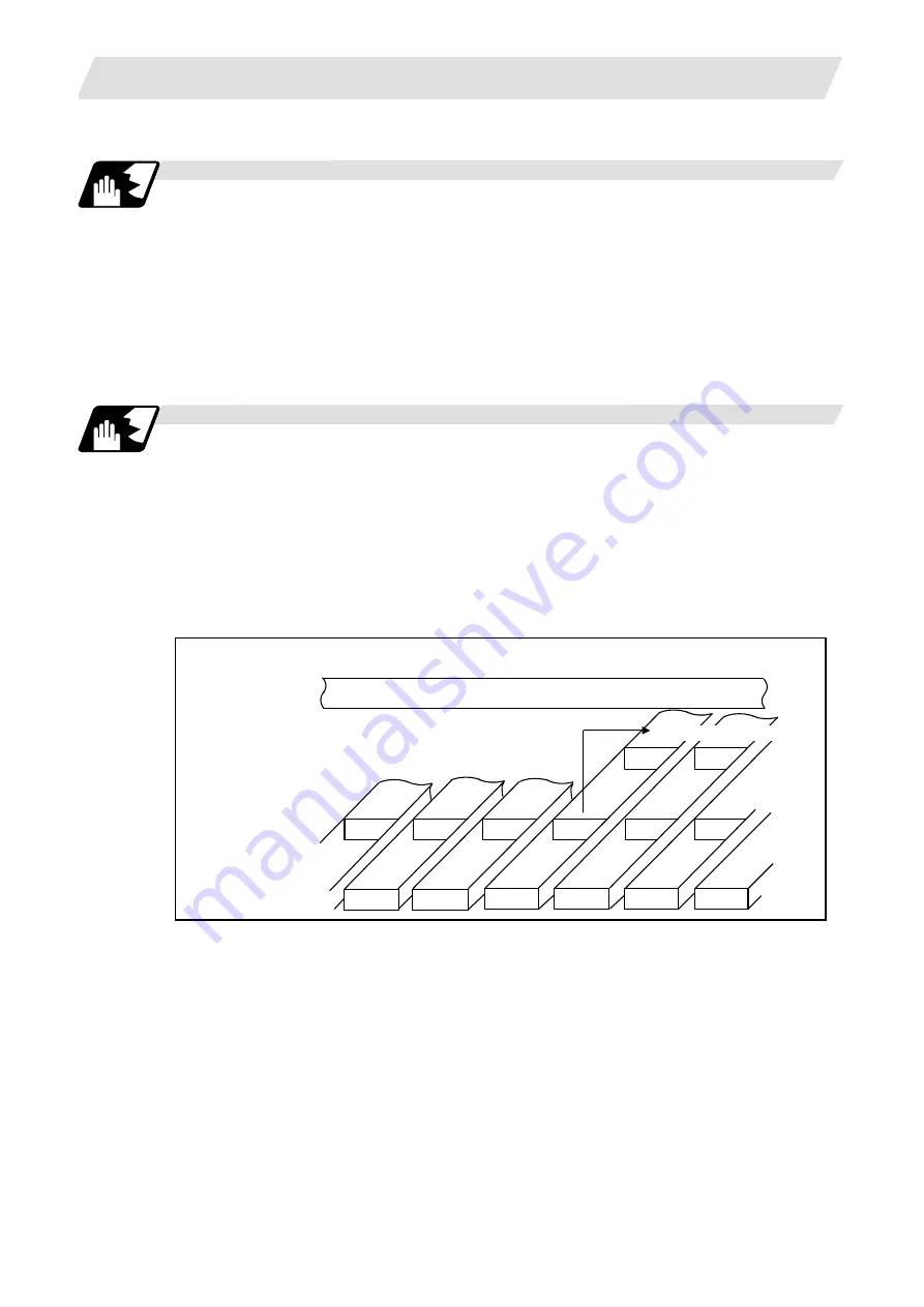
Control mode transition diagram
Machining program
Pre-read buffer
Execution block
T__; S__;
T__; S__;
G00_;
G00_; G41_; G01_; G02_;
G02_;
G01_;
G41_;
T____;
S____;
G00____;
G41____;
G01____;
G02____;
G01_; G02_;
Start of pre-reading 5 blocks
There are two ways of starting the compensation operation: type A and type B.
The type can be selected with bit 2 of parameter "#1229 set 01". This type is used in common with
the compensation cancel type.
In the following explanatory figure, "S" denotes the single block stop point.


