7. Feed Functions
7.6 Feedrate Dsignation and Effects on Control Axes
116
7.6 Feedrate Designation and Effects on Control Axes
Function and purpose
It has already been mentioned that a machine has a number of control axes. These control axes
can be divided into linear axes which control linear movement and rotary axes which control rotary
movement. The feedrate is designed to assign the displacement speed of these axes, and the
effect exerted on the tool movement speed which poses problems during cutting differs according
to when control is exercised over the linear axes or when it is exercised over the rotary axes.
The displacement amount for each axis is assigned separately for each axis by a value
corresponding to the respective axis. The feedrate is not assigned for each axis but assigned as a
single value. Therefore, when two or more axes are to be controlled simultaneously, it is necessary
to understand how this will work for each of the axes involved.
The assignment of the feedrate is described with the following related items.
When controlling linear axes
Even when only one machine axis is to be controlled or there are two or more axes to be controlled
simultaneously, the feed rate which is assigned by the F code functions as a linear speed in the tool
advance direction.
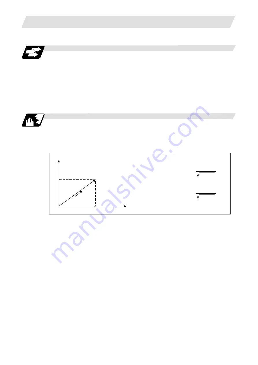
(Example)
When the feedrate is designated as "f" and linear axes (X and Y) are to be controlled:
P (Tool start point)
P
2
(Tool end point)
Speed in this
direction is "f"
Y
X
x
y
Feedrate for X axis = f x
x
x
2
+ y
2
Feedrate for Y axis = f x
y
x
2
+ y
2
When only linear axes are to be controlled, it is sufficient to designate the cutting feed in the
program. The feedrate for each axis is such that the designated rate is broken down into the
components corresponding to the movement amounts.


