

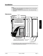


PL-565
Accumass BW500
Page 17
Inst
allat
ion
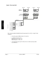
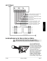
Interconnection
Note:
Wiring may be run via common conduit. However these may not be run in the
same conduit as high voltage contact or power wiring. Ground shield at one point
only. Insulate at junctions to prevent inadvertant grounding.
System Diagram
Note:
Typical system capability. Not all components or their maximum quantity may be
required.
belt scale,
see Specifications
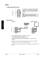
speed sensor,
optional,
see Specifications
customer remote
totalizer
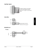
mA input from
customer device
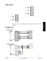
relay output, to
customer device
ACCUMASS
BW500
optional SmartLinx
®
optional analog I/O
mA output to
customer device
mA output to
customer device
optional fieldbus
connection
communication
ports can be
configured for
Milltronics
Dolphin, print
data, or Modbus
ASCII or RTU
protocol
auxiliary inputs
Содержание ACCUMASS BW500
Страница 1: ...ACCUMASS BW500 Instruction Manual PL 565 January 2001 CCUMASS BW500 33455650 Rev 1 2...
Страница 6: ...Page 6 Accumass BW500 PL 565...
Страница 12: ...Page 12 Accumass BW500 PL 565 Specifications...
Страница 28: ...Page 28 Accumass BW500 PL 565 Installation...
Страница 88: ...Page 88 Accumass BW500 PL 565 Parameters...
Страница 94: ...Page 94 Accumass BW500 PL 565 Operation...
Страница 106: ...Page 106 Accumass BW500 PL 565 PID Control...
Страница 110: ...Page 110 Accumass BW500 PL 565 Batching...
Страница 112: ...Page 112 Accumass BW500 PL 565 Certification...
Страница 140: ...Page 140 Accumass BW500 PL 565 Appendices...


