Operating Instructions - CPG2500
13
Precision Pressure Indicator
CPG2500
3.4 Display
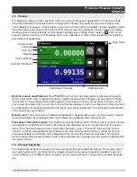
The display is made up of two sections. In the main screen (“Measure Application”), the left two thirds
shows the transducer channels that are configured for display, along with the pressure reading, units,
mode (absolute or gauge), channel label, an auto zero or tare button (if enabled) and any auxiliary indica-
tions that have been chosen. The right one third of the screen has Application Icons (“Apps”) for setting
viewing options, sensor settings, communication settings plus a “Page Down” button [ ] that, when
pressed, shows a second and third page of icons for calibration, remote communication error checking
and a leak test application.
Transducer Channels
Settings Apps
Channel label
and range
Auto Zero
Reading
Units and Mode
Auxiliary Indications
Page Down
Buttons, Labels and Windows: The CPG2500 touch screen has many buttons with relevant graphic
icons or text which, when pressed, will open a related window where changes can be made or informa-
tion viewed. Some of these buttons will toggle from one state to another, others present choices or dis-
play a numerical data entry screen. Text or icons that are displayed, but do not respond to being touched,
are called labels or windows. Operators will quickly become accustomed to the particular characteristics
of the frequently used buttons.
Main Screen: The main screen or “Measure Application”, appears after power-up. This screen contains
the channel frames and settings button. It will remain as configured after a power cycle.
Transducer Channel Frame(s): The transducer channel frames (left 2/3 of the screen) contain informa-
tion specific to a channel. Up to three channels can be displayed at once, two are shown in the picture
above. The channel frames are color coded with channel A - green, channel B - blue and the remote
channel - red. The optional barometer channel is sky-blue and the delta channel is yellow. If only one
channel is installed, a full frame will be displayed in the color of the channel connected. The channel
frame contains the pressure reading, units, and mode(absolute or gauge) plus any auxiliary displays that
have been chosen.
3.5 Chassis Assembly
The chassis assembly is the housing for the system and the removable transducers. The system has no
user-serviceable parts, and therefore the chassis should not be opened except by qualified repair per-
sonnel at Mensor or certified service locations for any reason except to change the removable transduc-
ers.
Содержание CPG2500
Страница 14: ...14 Operating Instructions CPG2500 Precision Pressure Indicator CPG2500 NOTES ...
Страница 47: ...Operating Instructions CPG2500 47 Precision Pressure Indicator CPG2500 NOTES ...
Страница 61: ...Operating Instructions CPG2500 61 Precision Pressure Indicator CPG2500 NOTES ...
Страница 67: ...Operating Instructions CPG2500 67 Precision Pressure Indicator CPG2500 NOTES ...
Страница 69: ...Operating Instructions CPG2500 69 Precision Pressure Indicator CPG2500 NOTES ...
Страница 85: ...Operating Instructions CPG2500 85 Precision Pressure Indicator CPG2500 NOTES ...


