


OPERATING CONTROLS AND PROCEDURES
CD25
3-10
Published 1-06-2017 Control # 579-01
Outrigger Controls
DO NOT
allow any persons to stand near extending or
lowering outriggers. Foot crushing could occur.
NOTE:
For maximum lift and stability, fully extend and
lower the outriggers. Be sure the crane is level
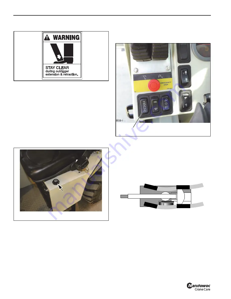
before lifting a load. The bubble indicator (1,
Figure 3-11) located next to the seat is to be used
to determine when the crane is level. The bubble
must be in the center of the indicator circle. Use the
outriggers to level the crane. If this is not possible,
reposition the crane until the bubble is centered.
If it is suspected that the bubble level indicator is out of
adjustment, verify and adjust the bubble level using the
procedures under
Steering Controls
The crane can be operated in three steering modes:
•
Two-Wheel Steering Mode
•
Four-Wheel Steering Mode
•
Crab Steering Mode
These modes are selected using the Steering Selector
Switch (1, Figure 3-12). Because proximity switches are
used in the steering system, after a steering mode is
selected and the steering wheel is turned, the steering mode
will automatically switch when the tires are aligned in straight
ahead direction.
The steering modes are shown in Figure 3-13, 3-14, and
3-15.
Two-Wheel Steer Mode
The front wheels steer the crane (Figure 3-13). The rear
wheels remain in the fixed straight ahead position. This
mode is used for highway travel and traveling at higher
speeds.
Four-Wheel Steer Mode
NOTE: DO NOT
travel at high speed with the crane in the
four-wheel steer mode. Possible tipping may occur
when turning.
The front wheels steer in the direction that the steering wheel
is turned and rear wheels turn in the opposite direction
(Figure 3-14). This mode allows for an extremely short
turning radius. It enables the rear wheels to follow the track
of the front wheels.
1100267
w0023
FIGURE 3-11
1
FIGURE 3-12
1
a0610
FIGURE 3-13
Reference Only
Содержание CD25
Страница 5: ...Operator Manual CD25 R e f e r e n c e O n l y ...
Страница 6: ...R e f e r e n c e O n l y ...
Страница 14: ...TABLE OF CONTENTS CD25 OPERATOR MANUAL TOC 6 THIS PAGE BLANK R e f e r e n c e O n l y ...
Страница 18: ...INTRODUCTION CD25 1 4 Published 1 06 2017 Control 579 01 THIS PAGE BLANK R e f e r e n c e O n l y ...
Страница 55: ...2 37 CD25 SAFETY INFORMATION 2 Published 1 06 2017 Control 579 01 8496 1 FIGURE 2 10 R e f e r e n c e O n l y ...
Страница 66: ...SAFETY INFORMATION CD25 2 48 Published 1 06 2017 Control 579 01 2 48 THIS PAGE BLANK R e f e r e n c e O n l y ...
Страница 100: ...CAPACITY CHART CD25 4 4 Published 1 06 2017 Control 579 01 THIS PAGE BLANK R e f e r e n c e O n l y ...
Страница 150: ...MAINTENANCE CD25 6 40 Published 1 06 2017 Control 579 01 THIS PAGE BLANK R e f e r e n c e O n l y ...
Страница 152: ...ADJUSTMENTS CD25 7 2 Published 1 06 2017 Control 579 01 THIS PAGE BLANK R e f e r e n c e O n l y ...
Страница 156: ...8 4 SPECIFICATIONS CD25 Published 1 06 2017 Control 579 01 Boom angle Maximum 80 Minimum 0 R e f e r e n c e O n l y ...
Страница 159: ...R e f e r e n c e O n l y ...
Страница 160: ...R e f e r e n c e O n l y ...