


3-3
CD25
OPERATING CONTROLS AND PROCEDURES
3
Published 1-06-2017 Control # 579-01
Left Dash Controls
Refer to Figure 3-3.
Defroster Switch
The Defroster Switch (3) controls the windshield defroster
fan.
Error Code Screen Toggle Switch
The Error Code Screen Toggle Switch (4) is a push-button
switch used to scroll through the error codes shown on the
LCD display, refer to
Diesel Exhaust Fluid (DEF) Level
Steering Select Switch
The Steering Select Switch (5) is used to select two-wheel
steering, four-wheel steering or crab steering. Refer to
Outrigger Extend/Retract Switch
The Outrigger Extend/Retract Switch (6) is used in
conjunction with the outrigger select switches, refer to
Outrigger/Jack Select Switches
, page 3-4. Press the top of
the switch to extend the outrigger/jack selected with the
Outrigger/Jack Select Switch. Press the bottom of the switch
to retract the outrigger/jack selected with the Outrigger/Jack
Select Switch. Refer to
, page 3-10. The
park brake must be applied before outriggers will function.
Headlights/Work Lights Switch
The Headlights/Work Lights Switch (7) is a three position
switch. Press the bottom of the switch to turn on the head
and tail lights. Press the top of the switch to turn on the work
lights. In the center position the lights are off.
Emergency Stop Switch
The crane Emergency Stop Switch (8) is used to shut down
the crane’s engine. Push the red button in to shut down the
engine, which illuminates the Emergency Stop indicator on
the indicator display. Rotate the knob and pull out to resume
normal operation.
8540
FIGURE 3-2
1
2
8464
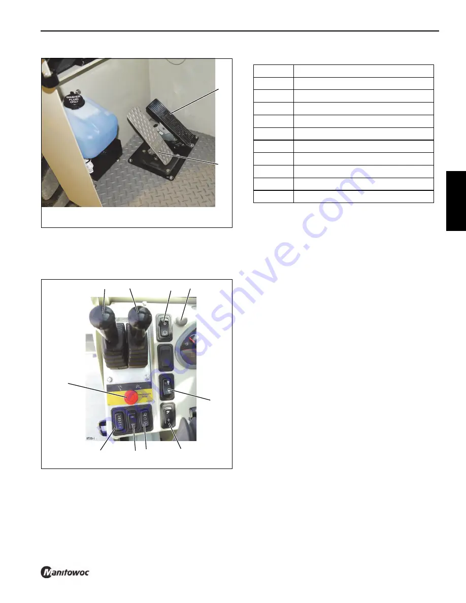
FIGURE 3-3
Left Dash Panel
5
3
1
2
7
6
4
8
9
10
Item
Description
1
Swing Control Lever
2
Telescope Control Lever
3
Defroster Switch
4
Error Code Screen Toggle Switch
5
Steering Select Switch
6
Outrigger Extend/Retract Switch
7
Headlights/Work Lights Switch
8
Emergency Stop Switch
9
Hoist Speed Switch
10
Two Wheel/Four Wheel Drive Switch
Reference Only
Содержание CD25
Страница 5: ...Operator Manual CD25 R e f e r e n c e O n l y ...
Страница 6: ...R e f e r e n c e O n l y ...
Страница 14: ...TABLE OF CONTENTS CD25 OPERATOR MANUAL TOC 6 THIS PAGE BLANK R e f e r e n c e O n l y ...
Страница 18: ...INTRODUCTION CD25 1 4 Published 1 06 2017 Control 579 01 THIS PAGE BLANK R e f e r e n c e O n l y ...
Страница 55: ...2 37 CD25 SAFETY INFORMATION 2 Published 1 06 2017 Control 579 01 8496 1 FIGURE 2 10 R e f e r e n c e O n l y ...
Страница 66: ...SAFETY INFORMATION CD25 2 48 Published 1 06 2017 Control 579 01 2 48 THIS PAGE BLANK R e f e r e n c e O n l y ...
Страница 100: ...CAPACITY CHART CD25 4 4 Published 1 06 2017 Control 579 01 THIS PAGE BLANK R e f e r e n c e O n l y ...
Страница 150: ...MAINTENANCE CD25 6 40 Published 1 06 2017 Control 579 01 THIS PAGE BLANK R e f e r e n c e O n l y ...
Страница 152: ...ADJUSTMENTS CD25 7 2 Published 1 06 2017 Control 579 01 THIS PAGE BLANK R e f e r e n c e O n l y ...
Страница 156: ...8 4 SPECIFICATIONS CD25 Published 1 06 2017 Control 579 01 Boom angle Maximum 80 Minimum 0 R e f e r e n c e O n l y ...
Страница 159: ...R e f e r e n c e O n l y ...
Страница 160: ...R e f e r e n c e O n l y ...